

Introduction: Arduino RC Car With Long Range and Custom Transmitter.


Hi! This is my first instructable.
In it I'll show you how to make a RC car with Arduino and the nrf24l01+ wireless module, or how to upgrade a cheap 27 MHz RC car.
The old RC car, which from I take the chassis, and the heli Controller, I got from a friend of mine, they weren't working anymore, the controller was from a 3.5 Channel helicopter. I decided to take off the old electronics from them and substitute with my own.
The vantage with the the nrf24l01+ is that it can transmit from more than 30 meters, from sources in the internet, I still not tested the maximum range that this setup can cover, but I have seen that is very far.
English isn't my mother language, so if you think that something is wrong, let me know in the comments.
Step 1: Gathering Stuff to the Controller


To make the controller I needed:
1 x Atmega8 (could be the Atmega328, but I think that it is too much power to this simple job).
1 x LCD module 16x02.
1 x 10kΩ trimpot.
1 x Nrf24L01+ wireless module.
2 x Push buttons with that screw.
1 x 1 kΩ resistor.
1 x 10 kΩ resistor.
1 x 16 MHz crystal.
1 x 5 V regulator (I used the 7805).
1 x 9 V battery.
1 x 9 V battery holder.
A small perfboard.
Jumper wires.
I used a LM317 adjustable regulator to do drop the 9 V from the battery to 3 V to the nrf24l01, but you can use a 3V3 regulator and don't use the components below.
1 x LM317 Regulator (No needed if you use a 3v3 regulator)
1 x 330Ω resistor
1 x 470Ω resistor
Step 2: About the Controller


The controller was supposed to:
- Read the state of the levers.
- Read the state of the backward button.
- Show some information on the LCD.
- Have a serial port to burn the code and debug.
- Have a port to easy hook the wireless module .
- Send information to the car through the wireless module.
The levers are read witch the analog digital converter(ADC), just had left the potentiometers that already were in the controller. There are two levers, so two analog pins had to be used.
As the forward lever, that before was the altitude lever in the helicopter, is not is the middle(the helicopter needs only one channel to control his altitude), one button was needed to tell the car to go back, when the button is pressed the lever is backward and when it is not pressed,the lever is forward.
A serial port cable was added to project, to program the controller just open the batteries case(no more) and connect the serial cable to one USB-USART converter, like the FTDI 232 or the CP2102 and program it with the Arduino IDE.
Step 3: Burning Bootloader on the Atmega

To use the Atmega as a Arduino and program it with the serial port is necessary to burn the arduino bootloader in it.
There a lot of nice instructables teaching how to do it. Some of them below:
https://www.instructables.com/id/Bootload-an-ATmega...
https://www.instructables.com/id/How-to-program-a-A...
https://www.instructables.com/id/Burn-BootLoader-in...
Just do the connections like the instructables above, select the Arduino ISP example in the Arduino IDE, burn it into the Arduino used to program the Atmega, then select Arduino as ISP as programmer in the Arduino IDE, and select "Arduino NG or older w/ Atmega 8" and then "Burn Bootloarder" in the Tools Menu.
You will need to use the picture above to know what pins in the Atmega match the Arduino standard pins.
Step 4: Making the Controller Board


I chose to make my own board, because i wanted something to hook easy the LCD display. A Arduino mini could fit well inside the controller if you don't want to make a board or aren't sure in how to do it.
As I said before, the Atmega8 was used because it could do everything needed well with it, its 8 KB of memory were enough to store the code and it had the serial and the analog-digital converter as all the Arduino boards based in the Atmega328, but you can use anyone these or the Atmega168 too.
Step 5: Connecting the LCD.


The LCD module,as can be seen in the first picture in the last step, is connected to the following pins:
LCD ---------------ATmega
VSS <------------>GND
VDD<------------>VCC( 5 V)
V0 <-------------->Center pin of the contrast trimpot
RS <-------------->Pin 8
RW <------------->GND
E <----------------->Pin 7
D0 until D3<----->Not Connect
D4 <--------------->Pin 6
D5 <--------------->Pin 5
D6 <--------------->Pin 4
D7 <---------------->Pin 3
A <------------------>1KΩ resistor to 5V
K <------------------>GND
The LCD will show some informations, I still working on what, I want to it show the speed of the car and maybe the battery charge, but in the codes attached it only shows the position of the levers.
Step 6: Making the Controller Regulators.


The controller needed two regulators, one to the board and LCD (5 V) and another to the wireless module(1.9 V up to 3.6V).
The 7805 was used to regulate the voltage to 5 V, required by the board and the LCD, just remember that looking to it, its first pin is the input, the second is the ground and the third is the output voltage.
To regulate 3 V for the nrf24l01 wasn't that easy, a adjustable regulator, the LM317, was used, looking to it, its first pin is the pin adjust, the second is the output voltage and the third is the input voltage.
The calculator in the site below was used to find the values to R1 and R2.
http://www.electronics-lab.com/articles/LM317/
R1=330Ω and R2=470Ω
If you have a 3.3 V regulator, like the LM1117, is easier to obtain 3.3 V that is in the voltage range supported by the nrf24l01+, just do the connections as with the 7805.
Step 7: The Nrf24l01+ Special Place


A port was made to hook the nrf24l01+. The pins used were:
Nrf24l01+ Atmega
VCC <----------> 3 V output from the regulator
GND <--------> GND
SCK <--------> Pin 13
MISO <--------> Pin 12
MOSI <--------> Pin 11
CSN <--------> Pin 10
CE <----------> Pin 9
IRQ <--------> Pin 2
See the pic on the step three to know whats pins on the Atmega are the pins above.
One square hole was made in the controller to fit the socket, making easy to connect the wireless module.
Step 8: The Serial Port


One cable was made to easy program the Atmega with the Arduino IDE. Just left the pins 5 V, GND, RX(Pin 0) and TX ( Pin 1) to connect a one USB-Serial TTL converter. The converter that I used is based on the chip CP2102, but there are many others, based in the FTDI232 and the PL2303.
Step 9: Putting the Controller Together.


All the wires were soldered in their places, as the first picture in the step four. The board was screwed in the controller, after this the controller was screwed leaving the serial cable and the battery connector in the battery olden place, this way, to burn the code in the controller, just open the battery door and pull the serial cable.
Step 10: Gathering More Stuff, to the Car Now.


These are the things that I used in the car :
1 x Arduino Nano Board.
1 x Mini Breadboard.
1 x H Bridge module.
1 x Li-po 11.1 V battery.
1 x Adjustable Regulator buck (step down) with LM2596.
1 x 9 V battery.
1 x Nrf24l01+ wireless module.
1 x Micro servo.
Jumper cables.
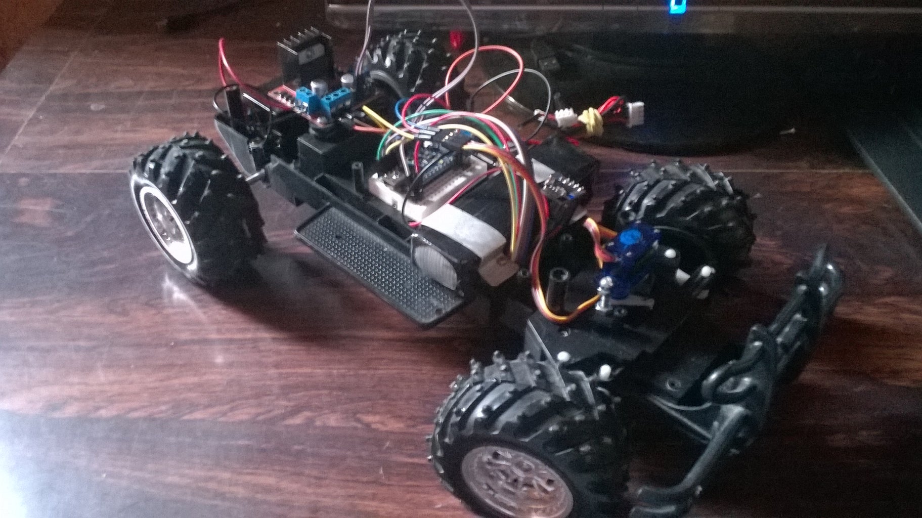
Step 11: About the Car

The Arduino nano was used to control the car. A H bridge module was used to control the Forward-Backward movement and a micro servo replaced the steering motor from before.
The steering motor that I take off of the chassis could be used, but I selected to use a servo, because this way is possible to have many many options of steering(angles), and not only left, right and center.
One Lipo battery of 11.1 V was used to power the motor and H bridge, while a 9 V battery was used to power the Arduino, nrf24l01+ and the micro servo. The 11.1 Vbattery could fry the motor, I used a regulator to drop the voltage to 6 V, the original voltage used in the olden electronics.
Step 12: Changing the Steering Motor With a Servo


The old steering motor could reach only three positions: center, full left and full right. As we know, the servo could reach a angle between 0° and 180°, this was is possible to select a angle to car take, instead of only three positions.
Step 13: Mounting the Arduino Nano


One mini breadboard was screwed to the chassis, it already had holes, I just used a Dremmel to make holes in the chassis.Then the Arduino Nano was mounted in the mini breadboard, male to female cables were used to connect the other components to the breadboard.
Step 14: The Batteries


Two batteries were used in the car, one of 11.1 V lipo and a of 9V.
The 11.1 V battery,used to power the motor and the H bridge, was fixed in the car with two aluminium pieces that were screwed in the chassis, this way, is easy to put and take the battery.
The 9 V is smaller, and was placed in the compartment where the olden battery were placed. This battery is used to power the Arduino,the servo, and the nrf24l01+.
Why not use just the 11.1 V battery?
This battery fried my first and loved Arduino, the high current in the cables burned my fingers (not too serious).I think that I reversed the polarity from the battery. After this accident I never more used it to power my Arduinos, but you can, if you want, use only one battery to power all the electronics in car.
*An advice* If you are sleep or tired, is not the good time the make or diy something, go get some rest and after that you will be ready to work well and be creative ;).
Step 15: The Adjustable Regulator


The regulator module is used to drop the voltage of 11.1 V in the battery to 6 V needed by the motor. The voltage of 6V was the original voltage in the 27MHz old electronics. One diode was soldered to the module to avoid damage if the polarity is accidentally reversed.
Step 16: The H Bridge.


The H bridge is used to control the motor with the Arduino, the Arduino digital outputs haven't enough current to drive motors, so a H bridge is used to drive and select what way the motor spins.
Remember to connect the grounds between the Arduino board and the H bridge.
Two motors could be used with this H bridge, but just one was used because the steering motor is the servo.
Step 17: Connecting the Nrf24l01+


The nrf24L01+ was connected to the Arduino through jumper cables, the pins used were:
VCC <--------> 3V3 Pin on the Arduino Nano.
GND <--------> GND
SCK <--------> Pin 13
MISO <--------> Pin 12
MOSI <--------> Pin 11
CSN <--------> Pin 9
CE <--------> Pin 8
IRQ <--------> Pin 10
The nrf24l01+ can not be connected on the 5V pin, only its digital inputs are 5V tolerant, if you put 5V in the VCC pin the module can be fried.
Step 18: Testing the Communication and the H Bridge.
The video shows the H bridge test, with the wireless link. The green button is the button that tell the car to go backward. As you can see the motor worked well.
Is hard to film and use the controller at the same time;)
Step 19: Connecting the Servo.


The servo was connected in the following pins:
Servo---------------------------Arduino.
Power(red wire) <------------>5V
Ground(brown wire)<-------->GND
Signal(orange wire)<--------> Pin 6(PWM)
Step 20: Testing Communication and the Servo.
Testing the steering servo through wireless communication.
Step 21: The Controller and Car Codes.
I'm not a code master,I confess, but these codes are working.I just modified them to fit in my project.

Step 22: Done!
That's it. If you have any doubts about this project, let me know in the comments.

Participated in the
Wheels Contest

Participated in the
Remote Control Contest

Participated in the
Battery Powered Contest


