

Introduction: Arduino Basics Part 2

Hi , this is the second part of the previous guide . In this guide I'll introduce some other 'basic' codes and general uses . The fact that some sensors are 'basic' doesn't certainly mean that they don't get complicated . Even a basic component - like a photo-transistor (IR receiver) can become quite complicated in some cases . But , this a basic guide (the ones that are quite boring for more professional people) .
I will use an Arduino (Uno , but any 'clone' or other board would work) , a 'computer' and the cable , an LED with a 220 Ohm resistor (NOT optional . Not using a resistor may not harm the LED but at some point deals little damage to the board ) , a 1602 Display with I2C board , an LDR (light dependent resistor) , breadboard and as the key component , Jumper wires . I'll try to make a guide for making them , but I don't think a little thing like this would be a single guide itself .
If you notice any mistake , any kind , I'd be more than grateful to hear it (and fix it)
Step 1: AnalogWrite

analogWrite , and read , is quite similar to the digital counterparts but there are differences . The first one is the pin limit . 20 of arduino uno pins are capable of digitalRead-ing and digitalWrite-ing , but only 6 can analogRead and 5 can analogWrite .
Let's ignore analogRead for now .
analogWrite is the code used . The option is called PWM , pulse width modulation , and a short explanation would be sending shorter / longer frequencies of pulses , to make a variable output : like , make an LED make little light . The pwm on Uno/Mega/Yun is not true analog , it only has 255 + 1 (0) possible modes : 0,1,2,...,255 whilst the true analog -DAC- on Due / Zero allows more than 4,000 possible modes , which allows these board to be able to play music .
Now about the code .
analogWrite , is used generally like this :
analogWrite([name],[value]);
instead of [name] , we should place a declared name , or pin .
instead of value , we place a number which can be 0,1,2,3,...,255 .
analogWrite(LED,0) is the same as digitalWrite(LED,0) , and , analogWrite(LED,255) is somehow the same as digitalWrite(LED,1) .
But , what if we wanted to analogWrite(LED,73) ? The simplest way to do so is to use analogWrite .
Use the code attached . nov02a is the sketch name .
The LED blinks , but when it turns on , it's half-lit . That's because we're giving it a low value .
Now modify the analogWrite , delete the 73 and type 255 . LED should blink fully lit .
If there are any problems :
make sure you've connected the LED to the right pin , 3 if you're using this code .
make sure the LED is in the right way .
make sure the LED is in well condition .
make sure wires and resistors are working .
make sure the code is compiled completely .
Attachments

Step 2: Working With I2C 1602 Displays
This is a simple thing to use , and a very useful one . They just need 2 of your arduino wires (the I2C , which is useful but the Uno has one pair . Analog 5 is SCL and 4 is SDA . Unlike serial , connect SDA to SDA and SCL to SCL . (in serial , TX is connected to RX and RX to TX)
Make sure Vin and Gnd are connected the right way . Reversed SDA SCL won't deal any damage , but reversed voltage can be bad . after you connect the display , the back light should turn on . Turning the potentiometer can change the contrast but that's for better quality , nothing special .
Now , there are a lot of codes these things can handle . This one requires the LiquidCrystal library . A guide on installing libraries on arduinos :
http://arduino.cc/en/Guide/Libraries
Now , the # includes are for including libraries and their codes .
LiquidCrystal_I2C lcd(0x27,16,2); will set the LCD address to 0x27 for a 16 chars and 2 line display , which I have no explanation about it . We should memorize these , un-learn-able .
The code itself with these is simpler than the Blink . after void setup , there is a code :
lcd.init();
which initializes the display , sort of important .
then , either in loop or setup , we just say :
lcd.backlight();
lcd.print("[words]");
which is fairly simple . Now , instead of [words] we just type something . This is a list of codes supported (won't discuss them now) :
LiquidCrystal()
begin()
clear()
home()
setCursor()
write()
print()
cursor()
noCursor()
blink()
noBlink()
display()
noDisplay()
scrollDisplayLeft()
scrollDisplayRight()
autoscroll()
noAutoscroll()
leftToRight()
rightToLeft()
createChar()
A starting code is attached .
Step 3: Making Variables
Making a variable , is the most important work . It is very important to learn it before analogRead (and digitalRead , which is usless )
The simplest way to make a variable :
1- before the setup , where names are declared and libraries are imported , write :
int [variable name] = 0;
this will make a variable but with size limits . You can use different data types for bigger values .
2-in the loop , at the beginning , write :
[variable name] = [how variable is calculated]
for example , a digitalRead or analogRead or anything else .
To declare analog pins in arduino , we can use :
int [name] = [number]
Step 4: Reading Value and Printing on Serial

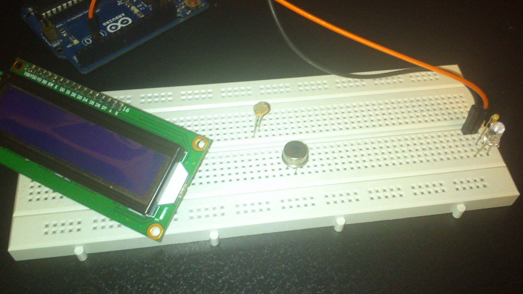
In this step , we will read an analog value , save it in a variable and print the variable in the display . We can use the LDR .
Now , place the LDR on your breadboard . Follow these steps :
Connect +5v to one of LDRs pins ;
Connect analog 3 to the LDRs other ;
Connect GND to the same pin as analog 3 ;
Use a 220 Ohms between LDRs pin and analog 3 .
Now , upload the attached code . I'll explain serial in the next guide .
Now open serial monitor , 9600 baud rate . You will see a value appears . After some seconds , another one does .
The value is based on the light the LDR receives .
Explanation on the code is given in comments .
Attachments
Step 5: Problems
Some problems happened during this instructable , and the final step was going to be about printing variable values on the display , but because of some reasons , it didn't work .
I tried a lot to delete everything which is not related but it didn't work for the pictures , and you might see some text about PIR sensors , which I might not have seen to delete . Sorry about those . I'll delete them if I notice them .
If you have any questions , feel free to ask .
Possible problems are :
Breadboards : make sure everything is connected
Power : make sure arduino has enough power
Code : review your code
I will try to continue the guides , and some good new projects are coming , but they are a bit long so they slow me down .
If you liked this instructable , I'd be grateful if you'd spare a moment in voting .

Participated in the
Microcontroller Contest

Participated in the
Tech Contest


