

Introduction: Arduino Binary Clock!
Better binary than the others I looked at!!
I prefer the full binary output for the sec/min/hr (rather than "Binary Coded Decimal" with just minutes and Hours.). I like to see the binary seconds ticking!!
I'm using code for the UNO!! (and Nano!!)
Yes, there are enough pins on the UNO :)
Hardware required:
- an Arduino Uno (or Mega or Nano)
- 17 LEDs (groups of 6/6/5 if you want different colors for HRs/MINs/SECs)
- 17 resisters for the LEDs *IMPORTANT*
- 35 jumper wires
- Breadboard
When complete, it will display time as binary for SEC / MIN / HR.
This is different than many of the others which use BCD (Binary Coded Decimal). This one sets the numbers using only one row of LEDs. I like this setup more because it is not mixing binary and decimal together.
- Step 1 is for hardware connections
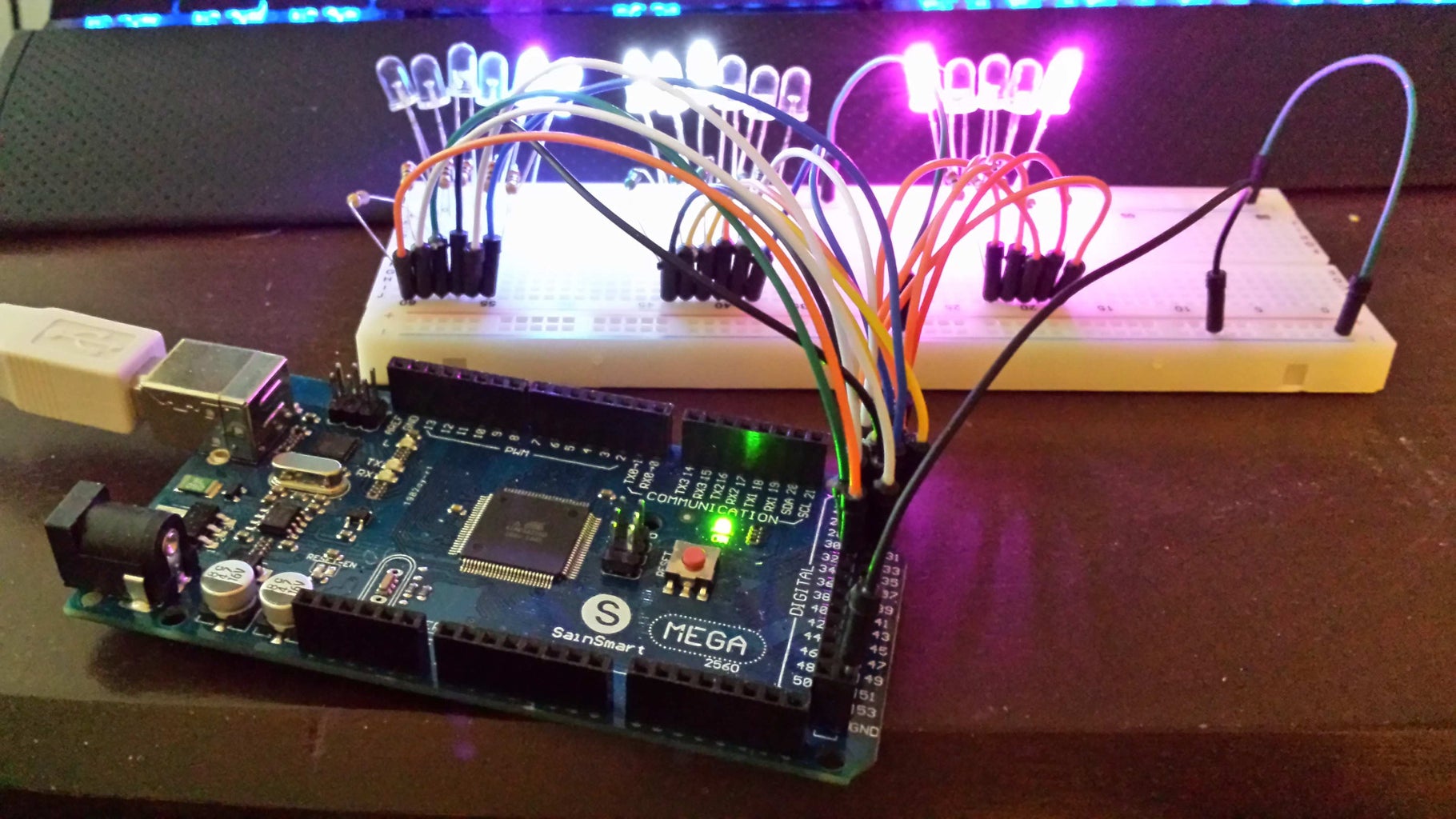
- Step 2 is for Programming V0.1 (top picture)
- Code is also included on step 3, please post any issues!
- Step 3 is for programming and circuit enhancements - Added timing code and upgraded wiring to include dimmed LEDs to allow for reading the LEDs in the dark!
*Uses an on-board Nano! - Step 4 will link to the 3D print and the $5 solar cell, a couple pics up now, links soon!
Step 1: Connect Hardware (V0.1)

Connect Hardware (using breadboard)
- Arduino UNO (Mega can be used, but it would use different pin assignments)
- 17 LEDs
- 17 Resistors
- 35 Jumper wires
- Connect 17 LEDs from (-) ground to the board in groups of 6, 6, 5.
- Wire resisters for EACH of the LEDs.
- Connect to Arduino UNO pins as shown.
- Connect ground to common ground for all the LEDs.
Power will come from the pins through the resisters to the ground through the LEDs, do not need to wire anything else!
*WARNING* If you do not use the proper resisters with the LEDs (with one for each), you may damage the LEDs.
*NOTE* Adjust the brightness of the LEDs by putting higher value resistors on any that are too bright!
Step 2: Program and Run Arduino Code

Load the code on your Arduino!
Download the text file, upload to your UNO using the IDE.
Couple notes:
- The millis() function is critical for counting time, it is not good to count time using delay().
- Most accurate time will be from a RTC (Real Time Clock) which can compensate for temperature changes (and has a battery in case of loss of power).
- The DEC to BIN conversion is very easy, 4 lines to write to pins (could be two).
- I need the delay() line near the end in order for the simulation to run acceptably, it is not required for the hardware version.
- If you wanna see it run, but don't have the hardware, you can see it on the simulator from the link below :)
Comment if you need help!
Here's the simulation!!
http://123d.circuits.io/circuits/645817-binary-clo...
Attachments

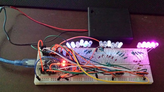
Step 3: Upgrade Wiring and Programming for V0.3


OK, some enhancements!!
First off, the programming is very similar, but is running on the Nano now with the hardware instead of the simulation :) (I also have a new simulation at this link it you want to look at the new one http://123d.circuits.io/circuits/649386-binary-cl... )
The changes to the wiring are:
- Incorporated an on-board Arduino Nano.
- Add 3.3v power through a higher value resistor and a diode for the "OFF" LEDs
The purpose is to be able to count the "OFF" LEDs in the dark! - Added code for jumpers / buttons to allow setting the time without reprogramming
I am using jumpers at the moment because I don't have any buttons on-hand! - Added power supply from a battery pack (think I'll try a solar power cell later!
- Dimming the display!
-1-
Installing the Nano is easy! Just plug it into the board!! (though you will need to re-wire the components)
*NOTE: I shorted the ground pin to power by brushing a jumper on the ground pin ... I needed to replace the Schottky Diode (it fried) to get power again from USB, be careful, do not touch power to ground! (best to leave off when wiring and check the circuit before powering!).
-2-
To provide a dimmed "OFF" state for the LEDs (to read them in low light), I needed to move all the resistors to make room for a diode and another wire for the low level power.
The circuit is revised so that the "LOW" power goes from the 3.3v Nano pin through a higher power resister (about 47k depends on the individual LEDs). A diode is in front of the "HIGH" resistor to flow current through the LEDs since the Nano pins are set to ground (0v) when they are off.
"HIGH" power goes through the diode and then through the LED.
-3-
I coded the jumpers to pins 0&1.
BOTH PINS NEED to be GROUNDED to keep time. The timer begins adding +1 for each 1/2 second, but then speeds up until adding +1 each 1/10 sec. To set the hours, I disconnect ground from pin 0 and to set minutes, I disconnect ground from pin 1.
Since these pins will interfere with downloading a program if they are grounded they need to be disconnected to program the Nano.
-4-
5V power source through the USB connector :)
I think I'll drop $4 on some cheap solar lights to make a solar power cell.
-5-
Dim all the lights together by adding resistance to the ground! I put this in the circuit diagram showing the ground going through a potentiometer before going to the ground rail. Adjusting the dial will reduce the overall voltage for the LEDs.
Thanks if you read up to here!
I expect to be adding more steps with solar power, diagram to build from "scratch" using the Mega chip instead of the full blown Nano, diagram for prototype perf board / PCB and 3D prints for the enclosure!
Attachments
Step 4: 3D Print and $5 Solar Cell! Coming Soon!


Here are pictures of the initial development for the 3D printed "minimalist" frame and the $5 solar cell.
I'll post them in separate instructables link will be added below soon!


