

Introduction: Colour Reading


Colour reading is a real issue for industrial models.
I've been working on it for more than 12 months now, since December 2009.
After many months of hard work,
• starting with the standard colour reader (season 1 ) with features a red LED,
• adding extra light from bulb lamps (season 2 ),
• using a powerful external white LED lamp (season 3 ),
• changing the built-in standard red LED for a white LED (season 4 ),
• I decided to go digital with an I2C 4 channels 10 bits sensor.
There are two challenges:
• manage the I2C sensor on Arduino,
• pass the information on to the fischertechnik controller.
Step 1: Technical Solution


On the Arduino side, I'm using:
• Inventor's Kit for Arduino (Sparkfun KIT-10173 )
• Logic Level Converter (Sparkfun BOB-08745 )
• Color Light Sensor Evaluation Board (Sparkfun SEN-08663 ) based on Avago ADJD-S371-Q999
• Opto-isolator Breakout (Sparkfun BOB-09118 )
The Avago ADJD-S371-Q999 is a four channels, red, green, bleu and clear, 10 bits colour sensor with built-in white LED.
On the fischertechnik side, I'm using
• a Robo TX controller (here or there )
• one switch
• three lamps
The Robo TX controller is I2C capable but, as at today, this feature is under development. So connecting the Avago sensor directly can't work!
See here for a short comparison between the Arduino and the Robo TX controller.
Step 2: Arduino Side - Hardware


I use the following colours:
• red cable for 5V
• black cable for ground
• blue cable for I2C SCL
• green cable for I2C SDA
• white cable for D0
• yellow cable for D1
I provide the step-by-step cabling:
1• empty board
2• power and I2C connections between Arduino and logic level connector
3• power connections between colour sensor and logic level convertor and 5V for the built-in LED
4• I2C connections between colour sensor and logic level convertor
5• digital connections between Arduino and opto-isolator
6• cables from opto-isolator to the fischertechnik TX controller
Step 3: Arduino Side - Software

Arduino code is based on a library for the sensor. The code is available here in the Attachments section at the bottom of the page.
I highlight the most interesting parts from the four sections of the Arduino sketch:
1• Call of libraries
#include <Wire.h>#include "I2C_RGBC_Reader.h"
2• Definition of variables and constants
I2C_RGBC_Reader myRGBC_Reader;
3• the setup() procedure launches the colour reader and calls the standard calibration
myRGBC_Reader.begin ();
myRGBC_Reader.standard ();
I2C address is set and standard calibration are sent to the colour sensor.
4• the loop() procedure includes two key parts: a memorise() function learns the colours
Serial.println("0..3 learn");
Serial.print("> colour object required\n");
while (!Serial.available());
myRGBC_Reader.memorise ((command - 0x30));
and a getRGBC() function reads the cylinder while a recognise() function identifies the colour.
myRGBC_Reader.getRGBC (r, g, b, c);
myRGBC_Reader.recognise (n, p);
Recognition is based of distance calculation: the nearest memorised colour from the read colour is selected. A proximity index is also provided: it should be smaller than 100%, otherwise returned colour confidence is low.
The colour n is then coded into 2 bits and sent to the TX-C.
• case=0 no object i1=0 i2=0
• case=1 blue colour i1=0 i2=1
• case=2 red colour i1=1 i2=0
• case=3 white colour i1=1 i2=1
if (n==0) {
digitalWrite(out1pin, LOW);
digitalWrite(out2pin, LOW);
}
else if (n==1) {
digitalWrite(out1pin, LOW);
digitalWrite(out2pin, HIGH);
}
else if (n==2) {
digitalWrite(out1pin, HIGH);
digitalWrite(out2pin, LOW);
}
else if (n==3) {
digitalWrite(out1pin, HIGH);
digitalWrite(out2pin, HIGH);
}
else {
digitalWrite(out1pin, LOW);
digitalWrite(out2pin, LOW);
}

Step 4: Fischertechnik Side - Hardware


The fischertechnik hardware building has clearly two parts:
1• inputs from the Arduino
2• fischertechnik system devices as switch and lamps
The inputs from Arduino use the same colours as previously
• red cable from opto-isolator power to fischertechnik +9V
• black cable from opto-isolator ground to fischertechnik ground
• white cable for from opto-isolator EXT1 to fischertechnik i1 input
• yellow cable for from opto-isolator EXT2 to fischertechnik i2 input
Then, the fischertechnik controller is connected to other devices including an emergency switch on i8, a blue lamp on m1, a red lamp on m2 and a white lamp on m3.
Step 5: Fischertechnik Side - Software


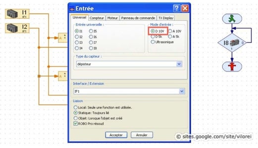
fischertechnik models are programmed using the Robo Pro software (more here and there ), which provides a nice graphic interface.
Unlike Arduino, the TX controller features 8 universal inputs, analog or digital, 5 kΩ or 10V. So i1 and i2 inputs are declared as digital 10V inputs
Basically, the program translate a 2 bits input into 4 cases
• i1=0 i2=0 case=0 no light
• i1=0 i2=1 case=1 light m1=blue
• i1=1 i2=0 case=2 light m2=red
• i1=1 i2=1 case=3 light m3=white
An loop checks the emergency button i8.
Attachments
Step 6: Results


When a cylinder is presented on the sensor, the corresponding colour light is tuned on. No cylinder, no light!
The validation protocol includes three majors criteria:
• Colours are clearly recognised.
• The separation criteria is met.
• The sensor is immune from ambient lighting impact.
During all the tests I conducted, colours were always identified rightly.
In industrial parlance, this sensor is capable!
Participated in the
Microcontroller Contest


