

Introduction: Arduino Weather Station With RF433 MHz Modules


In this project I will show you how make two Arduinos talk to each other using RF frequency (wireless)
In the past I published four instructables that lead to this one :
The first two are about connecting a serial LCD with I2C to an Arduino UNO and a NANO
https://www.instructables.com/id/How-to-connect-a-s...
https://www.instructables.com/id/How-to-connect-a-s...
Another one showing how to use an LM35 temperature sensor with Arduino and an LCD
https://www.instructables.com/id/Display-temperatur...
And the last one is about using an LM35 temperature sensor without an LCD
https://www.instructables.com/id/How-to-display-tem...
Now I will use the knowledge in all these project and improve on them by making one Arduino send data to another Arduino wirelessly using an RF433 module and displaying it on I2C serial LCD.
Step 1: What Is Needed for This Project

Here is what you'll need for this project:
- 2 Arduinos, I am using an UNO and a NANO
- 2 Solderless breadboards
- A pair of RF433 Wireless TX-RX
- An LM35 temperature sensor
- An I2C serial LCD
- And a bunch of jumper wires
The RF433 Wireless TX+RX Pair are ideal for this project because they have a good range about 14 meters or 47 feet without antenna and 31 meters or 102 feet if you attach a 17.4cm antenna on both modules. Those numbers are in theory, real life result may vary according to voltage, temperature, walls etc.... but the idea is that they are great for a 1$ piece of electronics.
Step 2: Connect the Uno, LM35 and the Transmitter


I selected the UNO for this part because it can be powered by an external source.
First connect the GND and the VCC from the Arduino to the bread board
Insert the LM35 on the breadboard and connect the GND and the VCC (see picture for the location of the VCC and the GND pin on the LM35) The middle prong connects to PIN A0 on the Arduino.
If you reverse the GND and the VCC on the LM35, it will heat up and produce readings in the range of 300 to 500 degrees C. (if this happens avoid touching it with your hands)
Insert the RF433-TX module, place it facing you and Pins should be DATA, VCC, GND from left to right (see picture)
Connect the VCC and the GND to the +/- rails on the breadboard and the Data pin connects on digital pin 12 on the Arduino.
This is it for this part, next I will discuss the transmitter sketch.
Step 3: Transmitter Sketch
Start by loading the VirtualWire library which is responsible for communication between the RF433 TX and RX modules
#include <VirtualWire.h>
Next I will define few variables
float temp; This will be the variable I will use to store the temperature reading<br>int sensor = 0; This is the A0 where the LM35 data pin is connected char msg[6]; This is a Char array called msg that I will use to transmit the data with
Next is the void setup
Here I will define the TX pin is on digital pin 12 on the Arduino and set the transfer rate to 2000 bps
vw_set_tx_pin(12); // Sets pin D12 as the TX pin<br>vw_setup(2000); // Bits per sec
In the void loop I read the temperature from the sensor and store it in the variable temp then convert it to Celsius by multiplying the result with 0.48828125
temp = analogRead(sensor);
temp = temp * 0.48828125;
Then I change the type of the variable temp from float to char and store the values in an array called msg to transmit it to the RF433-RX
dtostrf(temp, 6,2,msg);
The I transmit the data over to the RX
vw_send((uint8_t *)msg, strlen(msg)); <br>vw_wait_tx(); delay(200);
The transmitter code and the virtual Wire library are attached in this step.Rece
Attachments

Step 4: Connect the NANO, the Receiver and the I2C LCD
In this section I will connect the NANO with the LCD and the RF433-RX module
Plug in the NANO on the breadboard
Then insert the RF433-RX module
Connect the VCC and the GND from the RF433-RX to the NANO GND and VCC and connect the Data PIN (left most pin) to the digital pin 12 on the NANO
Connect the GND and the VCC from the I2C serial LCD to the GND and the VCC pins on the NANO, then connect the SDA to analog pin 4 on the NANO and the SCL to analog pin 5 on the NANO.
Step 5: Receiver Sketch
There is more action in this sketch:
First load the libraries:
#include <VirtualWire.h>
#include<Wire.h>
#include <LCD.h>
#include <LiquidCrystal_I2C.h>
Then define the variables: and initialize the LCD
#define I2C_ADDR          0x27        //Define I2C Address where the PCF8574A is<br>#define BACKLIGHT_PIN      3
#define En_pin             2
#define Rw_pin             1
#define Rs_pin             0
#define D4_pin             4
#define D5_pin             5
#define D6_pin             6
#define D7_pin             7
int I;
//Initialise the LCD
LiquidCrystal_I2C      lcd(I2C_ADDR, En_pin,Rw_pin,Rs_pin,D4_pin,D5_pin,D6_pin,D7_pin);
In the void setup I define the LCD, turn on the backlight, set the RX pin on digital 12 on the NANO, set the transfer rate to 2000bps and tell the receiver to listen for incoming transmission.
//Define the LCD as 16 column by 2 rows <br> lcd.begin (16,2);
//Switch on the backlight
lcd.setBacklightPin(BACKLIGHT_PIN,POSITIVE);
lcd.setBacklight(HIGH);
//Define the receiver pin and rate
vw_set_rx_pin(12); //Sets pin D12 as the RX Pin
vw_setup(2000); // Bits per sec
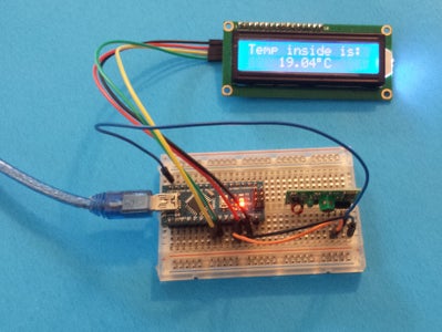
vw_rx_start(); // Start the receiver PLL runningIn the void loop, the NANO checks for transmission, and if it receives one, it prints "The temp is:" on the first line on the LCD and then prints the value with degrees Celsius on the second line
uint8_t buf[VW_MAX_MESSAGE_LEN];<br>   uint8_t buflen = VW_MAX_MESSAGE_LEN;

   if( vw_get_message(buf, &buflen) )
      {
        lcd.setCursor(0, 0);
        lcd.print("Temp inside is:");
        lcd.setCursor(3,1);

       for (i = 0; i < buflen; i++)
         {
           lcd.write(buf[i]);

         }

           lcd.print((char)223);
           lcd.print("C");
The code is attached in this step
Have fun building it


