

Introduction: Arrow Coffee Table


Welcome to this three legged coffee table build. Why three legs? Well mainly because I wanted to try it out, and I was attracted to the minimalist aesthetic. Also, it can be placed on very wonky uneven floors and still sit level without rocking. The disadvantage is, of course, that ultimate stability is reduced. But hey, this is an uncompromisingly artsy coffee table, and it wants one edge to be supported by a single big leg at a jaunty angle...
And anyway the weight of the big slab helps to keep things stable. Also, I figured that I could add cross support at the bottom of the big leg once I was done, if it needed it,
Step 1: Material Based Design


As usual this project was designed as a homage to the materials themselves. The slab was the end of a much longer slab I used to make the rails of this Warlock's Bed. This was one of the first things I milled using the chainsaw mill I made a couple of years ago.
I really liked the sycamore's grain pattern and light colour and what was left over seemed a perfect size for a coffee table. The only problem was that it had a rogue saw cut in one end of it. At first, I cursed myself for my careless sawing work and thought it would be a right pain. Later this was incorporated into the design of the leg joint, and is now probably my favourite detail of the table.
Apart from the top itself there are three other main components of the table, the legs, the 'aluminium feature joint', and the aluminium feet.
First, the legs: the tent poles I used for the two arrow shaft'esque legs have been hanging about the workshop for ages, waiting for a suitable project. They are anodized alloy, strong and light. Similarly I have been storing the lovely aged oak post for years, waiting for the perfect project.
Second, the structural aluminium insert was made from scavenged scraps aluminium, that had been building up ready for more casting experiments. Why not combine the awesome natural feel of solid wood with shiny modern aluminium? When I started posting pics of this build on the flowering elbow facebook page a friend said it reminded him of Hilla Shamia's aluminium-wood combo. That was very cool, but used a LOT of aluminium and I was no where near geared up for pouring molten metal on that scale. I wasn't so sure on the burnt wood look either. For that reason I ruled out solid cast aluminium legs, and pouring molten metal straight onto wood. Instead... Well, lets get to that in a later step...
Third, the aluminium feet, just sorta happened, as I wanted to continue the 'arrow' theme. You will see them in later steps too.
Step 2: The Big Leg Tenon


I fancied having this big old oak post I have been hoarding as a leg for the table. When I squared up the end on the mitre saw it was so pretty that I decided it had to be on display. That mean I was going to have to make it stick right through the thick 2" Sycamore table top. In other words a 'through tenon' was called for.
Contrary to my usual practice, I started by cutting the tenon of the leg, rather than the mortice in the top (it's usually easier to make a tenon to fit a mortice than than a mortice to fit a tenon).
I wanted to preserve as much of the end grain as possible, so only took off about 10mm from each side, to form a big square tenon. I wasn't sure how this would work out/ look with the crazy fissures in the oak, and thought I might have to take more material off, which is why I did this step first. Turned out 10mm was fine though. On to the mortice!
Step 3: The Big Leg's Mortice


The end grain of the leg is so exciting, it didn't deserve to be lined up with the sides of the coffee table's top in a 'standard' kinda way. I played about with various positions until happy and drew around the tenon to mark what I needed to remove.
This is such a big mortice, that I cut the majority of the waste out with a jigsaw (the 2" top was pushing it in terms of thickness, but it just about worked). Then I made a quick and dirty router template with some scraps of ply. I followed that with a pattern cutting bit (one with a ball bearing on top) to get a precise hole.
That just left me with some corners to carefully square up with the chisel...
Step 4: Tying the Leg Into the Table Top


Now the mortice is fitting nice, I wanted to somehow 'tie-in' the fissures in the end grain to the table top. This is more a metaphorical/aesthetic 'tie-in', in terms of strength a through mortice in a 2" slab should do fine.
With the leg dry fitted in the top, I pencilled on and rubbed out a few different designs, before settling on one that looked kinda like some hunting arrows. That I liked.
I drilled out some of the waste and cut the rest away with chisels.
Step 5: Making a Scale Template for the Insert


Now it's time to fill that arrow shaped hole I had formed. To do so I used the first top down photo, to created a print out. The ruler in the photo was to ensure it was exactly to scale. There are probably loads of clever ways to do this - here's what I did:
Using Paint Shop Pro I copied a section of the ruler and pasted into the same image so it effectivly extended the ruler, which now spanned the length of the photo. I recorded that total height in mm, and undid the paste to get the original image back. Then in the print dialogue I set the print size to the total recorded measurement and did my print.
I double checked the black and white print out with a real ruler against the printed one. All was well :)
Then I carefully cut out the shapes with some scissors and stuck it onto some polystyrene.
The idea being to make a mould for an aluminium casting.
Step 6: Hot Wire Cutter Interlude.


I needed a way to cut the foam pattern, so I made a very rudimentary hot wire cutter. The one I cobbled together from scraps was basically along these lines https://www.instructables.com/id/Hot-wire-foam-cutter/, except I didn't have a control dial.
To adjust the temperature I varied the current by changing the resistance of the load. I did this by changing the length of the nichrome wire (an old heater element). Put simply, the longer the wire the lower the temperature and the less current is drawn from the power supply unit (PSU). In my case the PSU was an old 12V ATX computer supply. It seemed to work very well.
After a bit of testing I had it setup ready to cut the Styrofoam pattern, but...
I found I couldn't accurately cut quick enough to avoid it burning irregular holes, so my first pattern was a bit rubbish. I de-tuned it a bit (lowered the temp) and my second attempt was better.
I was using some old polystyrene insulation off cut that had been knocking about - it wasn't ideal. Being both a bit dirty and too 'bobbly', or not dense enough. at this stage I didn't want to loose momentum with the table and ploughed on regardless!
Step 7: Prep for Aluminium Casting


Some trial and error was involved with this and the first couple of foam moulds needed to be scraped.
If I do any much more of this I will have to create a vertical wire with a fixed square worktable (like a bandsaw arrangement) to work with...
Once I had something I was roughly happy with, I hot melt glued some sprues on, put some sand in a bucket (top tip: don't use a plastic bucket), put the patterns on that and filled up around then with sand.
The observant knowledgeables among you will have noticed that I didn't uses any form of plaster coating on the pattern, as is normal. The reason: the foam is so rough anyway, I figured it wouldn't make a world of difference, and more importantly I really didn't want to wait another day or more while the stuff fully dried.
In practice this meant I was very unsure, right up to the moment I uncovered the result from the sand, if this pour would be a complete fail or just quite shabby...
Step 8: The Melt!


So I fired up the furnace, melted some aluminium, and poured. I very quickly had it overflowing from the top of the sprues... What happened? There must have been a sand cave-in, I thought. That would have plugged the flow of aluminium and ruined the whole thing. I had to go out for a run to let it cool and work off some of my anticipated frustration.
Hopefully, it goes without saying that this is all horribly dangerous. James and his cat should not be encouraged to melt metals without lots of research, and a very good knowledge of the safety precautions required...
Step 9: Uncovering the Casting


And then I used some pliers to pull it from the sand. Amazingly it actually came out ok!!!
I hacksawed off the sprues and tested it in the hole - not a terrible fit. This may work yet.
Step 10: Epoxy Up the Gaps


So I always knew the fit wasn't going to be totally exact. And that was fine because I thought a small amount of black epoxy fill mix (of my special sand epoxy recipe) would outline the aluminium and set it off nicely. I going to need some to fill the other small cracks in the endgrain anyway...
To make the epoxy easy to work with I mix the hardener and resin first, then add pigment (in this case old black toner from a laser printer) and then mix in the sand until its an nice workable putty paste.
Step 11: Making It Flush With the Surface


LOTS OF SANDING AND SOME GRINDING.........................
Saying any more will bring back the horror.
Step 12: The Flush Finish


Ok so I like the overall effect.
There are few things I mucked up.
1. The black epoxy seems to have been a bit too runny and was sucked up the grain of the table top a bit - making dirty looking marks in some places around the aluminium - these will never go away, however much I sand :(
2. I was a bit heavy handed with the mallet when I was putting the insert in and a very small crack developed at the tip of one of the arrowheads. Sigh!
But still, the overall finish has a handmade look that is really quite striking. So in my book the big leg/table interface is still kinda cool.
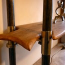
Step 13: The Arrow Legs


So that's one leg done. We need at least two others for this baby to stand.
At this point I am firmly gripped with the idea that the table is going to be united about the theme of arrows! I had some scrap aluminium tent poles I was given that I thought looked cool and like arrow shafts...
Only thing was they were not quite long enough, So I made these mounting blocks to fit to the top, to hold them at a nice angle and all in line.
These blocks are joined to the top with a mortise and tenon. This time I made the mortises first and then made the tenons to fit.
Step 14: Tenoning the Arrow Shaft Holders.


There are many ways to make tenons and loads of excellent tutorials already so I'll just skim over my method.
Because I wanted the legs angled outwards, I cut the shoulders using the mitre gauge on the table saw. Setting the height of the blade controls the thickness of the tenon, so I always spend some time getting that just right - I use a callipers to measure the depth of some test cuts in scrap wood.
Once I have the shoulders cut I quickly double check the width of the tenon with the callipers. Then, if all is well, I cut the majority of the waste out on the bandsaw, cutting well outside the line, and then use the tablesaw again to trim off the excess left by the bandsaw. I find this approach saves on saw blade resharpening and dust barrel emptying compared to cutting it all on the tablesaw with many passes.
Step 15: The Arrowhead Feet


I decided to build on the foam casting experiment earlier and have the four shafts of the legs (the broken tent poles) come down to some cast aluminium feet. By securely constraining the four shafts at both the top and bottom the leg structure should be amply strong.
For this one I asked in PC World if they had an scrap polystyrene they could give me, and ended up with the piece in photo one. Looking at it I started to rethink my flat design, as I though I could use the ridge of the packaging.
The casting itself went pretty much as before, but with slightly less melty-bucket action.
Step 16: Finishing and Drilling the Foot Castings


Success!! Well sort of at least. The castings came out ok - check out the polystyrene texture in the close up pics.
Now we need to tidy up those castings a bit with a good old fashioned wire brushing. This is easier while they are still on the sprue - as this acts as a useful handle.
After that I cut them off, flatten the bottom a bit on the Mighty Disk Sander, and clamp it to an angling table, which in turn is clamped to the mill-drill's table. I needed the holes at an angle to go with the angled outwards legs I've been planning.
Once that's setup, I use an 8mm end mill (the poles are 8.5mm but whoever heard of half sizes in endmills?) to get the holes started in the slop of the aluminium. A standard drill bit would have just skidded down the slope and snapped. I use a fairly fast speed (1000rpm) and took it at a nice steady pace. I space each hole 11mm apart so that the four shafts of the leg will taper together slightly towards the floor.
Step 17: Expanding a Hole Tip


Ok so that left me with a 8mm hole and poles that were exactly 8.5mm diameter. Here a tip for these expanding hole scenarios.
You could chuck up your standard 8.5mm jobber bit and have at it - goodness knows I have done that plenty. What you will notice if you do it that way is that the bit will bite very aggressively, either wrenching your wrist (if using a hand drill), tearing out material around the surface of the hole, or pulling in and wandering uncontrollably - most likely a bit of all those. Sometimes that's manageable. Other times it's worth prepping a drill bit especially for expanding purposes.
Put simply, we need to grind the cutting edge so that it is no longer a positive angle that pulls the drill forwards. Instead we make that angle 90 degrees. A rotary tool like the dremal does this in seconds, as we only need to remove just enough material to change that angle. You may not want to do this with you new sharp bits, but it is an excellent use for all those old blunt redundant bits. See the photos for details.
Step 18: Cutting Shafts to Length and Gluing Up the Legs


Using a convoluted method, that I can't bring myself to go into here, I measured and cut the poles (removing the few broken splintered ends) and glued them into their respective holes. I used standard epoxy with a 'slow' hardener.
After glueing the shafts to the wooden mounts, and then the shafts to the aluminium castings, there was quite a bit left over, so I used that up on the mortices and glued the whole legs onto the top! Weeeha.
Step 19: Finishing the Surface


I sanded the surface nice and flat to 240 grit with the random orbit sander. Going to higher grits would make it shinier, but would make no sense with an oil based finish.
I used an eco-esque product called Osmo Polyx oil. I use it on most of my interior wood projects and I love it. I gave this three thin coats, rubbing it in with a clean rag.
The aluminium insert had special treatment - that was lacquered with a Chestnut Products brush on Acrylic Lacquer. It was quite tricky keeping the polyx oil off the alu and the lacquer off the wood, but it seemed to work.
Step 20: Coffee Time (concluding Thoughts)


After gaining some distance from this project I think it turned out right enough. At the time I thought the epoxy leeching around the insert, and the small crack there, was the ruin of it! But that's because it really wasn't part of the plan. Other people who have seen it have thought it was all part of the effect...
The Welsh Sycamore slab itself is quite awesome - it would be quite hard to not like something incorporating that. Knowing the tree it came from and having milled it with the chainsaw mill, and seasoned it for several years is a nice feeling too.
I kinda like the minimalist three legged design, and that it will sit flat on any uneven floor, but it is quite a bit more unstable than it would be with four legs. Still, I feel like the materials really worked with this design, and it doesn't seem wobbly enough to justify making a cross support on the bottom of the single leg.
I hope some of this was of use to you. If so please, come and like my facebook page https://www.facebook.com/floweringelbow where I post up current builds and experiments.

Participated in the
Epilog Contest VII


