

Introduction: Atmega328p Companion
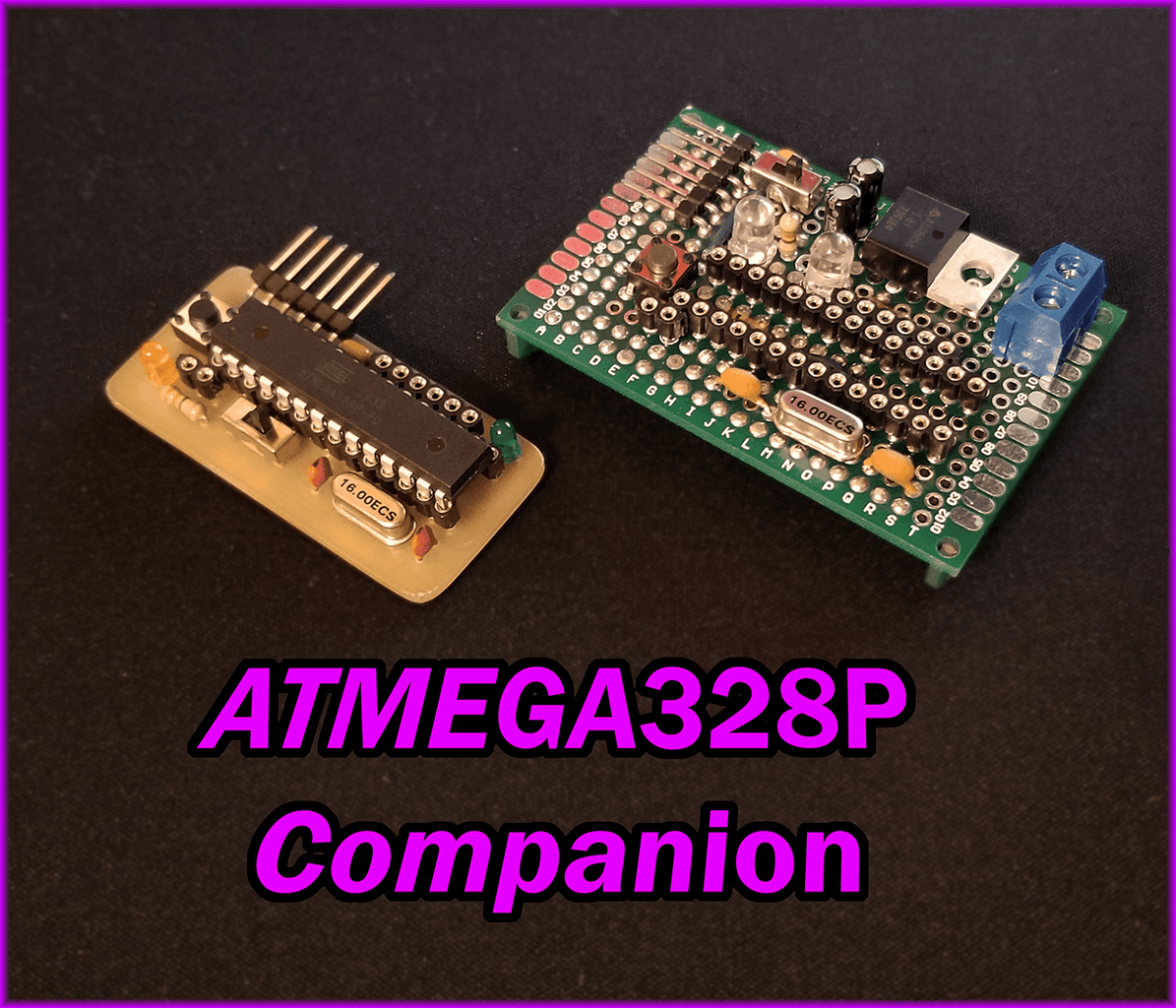

ATMEGA328P Companion: The Bootloader and Programmer Module
If you're like me, you're addicted to projects and Arduino. However, if you've done a number of projects with an Arduino as the brain, you've probably started to get sick of looking at the Arduino board as a whole, cluttering your project and overall just looking bad. As such, I decided that I wanted to move from the Arduino boards to using just the IC.
Enter the atmega328p.
The atmega328p is probably the most prolific Arduino compatible IC on the market. It's by no means the cheapest or most powerful, however, when taking both of these into account, it is in my opinion the best performance per dollar. So are you ready to start making your projects look much more professional and less like a conglomeration of off the shelf modules? If so, read through this instructable and you'll get the necessary information to build your own module that will allow you to flash a bootloader to your target atmega328p, upload the blink sketch to ensure that things are working, and finally upload your own sketches for your individual projects.
Step 1: BOM and Tools
First things first, this instructable isn't going to be a step by step how to build manual, but instead I'm assuming that you know how to read a schematic and can translate that to a board. With that in mind, here are the necessary materials and tools:
Materials:
- 1x 40x60mm protoboard or PCB
- 1x 6pin male header (I used right angle males)
- 2x 14pin female header
- 1x 6pin female header
- 1x 2pin female header
- 2x 22pF capacitor (22)
- 1x 0.1uF capacitor (104)
- 1x 10kohm resistor
- 2x 330ohm resistor
- 1x LED (any color for power indicator - 3mm for PCB design)
- 1x LED (any color for digital pin 13 for blink sketch - 3mm for PCB design)
- 1x 16MHz crystal
- 1x slide switch
- 1x momentary push button
Tools:
- Arduino Uno
- Soldering Iron
- 6x M-M jumpers
- FTDI programmer
- USB cable that matches your FTDI programmer
- Arduino IDE
Step 2: Schematic/Layout


Attached to this step are the eagle files that I used. You're free to modify them and change them however you please. I did, however, design the board so that all of the traces are on the bottom layer so that it's easy to fabricate on a PCB mill (if you have access to one) with a one sided board. It's also on bottom so that it's easy to solder the components together.
If you want the PCB, however, just run the CAM to get the necessary gerber files for your favorite manufacturer. I like OSH Park because you just give them the board file and they run the necessary CAMs to get the files they need.

Step 3: Soldering


So there's three ways of making this board:
- Populating a PCB
- Populating a milled board
- Populating a protoboard
Populating the PCB is quite straight forward, and shouldn't give you any trouble as everything is labeled.
Populating a milled board also shouldn't be too difficult, as it is modeled exactly the same way as the PCB, except you don't have the markings, so follow along with the board file in Eagle to make sure you're putting things in the right place (particularly the polarity of the LEDs).
Lastly, populating a protoboard is the most thought intensive, however, it isn't terribly difficult. I have a few pictures on this step showing my protoboard version and how I fit everything. Note that the LM7805, the two 4.7uF capacitors and the screw terminals won't be on your board. I was playing around with the idea of having this have the capability to be externally powered, but once I started thinking about it, I decided it was ultimately a waste of board space.
Step 4: Bootloading
Setting Up the Bootloading Arduino:
So here is where you're going to need your other Arduino. First go here and download the files from this guy. At this point, the files are a few years old, but they still work great. Once you've gotten them downloaded, open optiLoader.ino and your Arduino IDE should prompt you to put it into a folder. Do so and then put the optiLoader.h file in the folder with the .ino. Now you're ready to upload that sketch to your bootloading Arduino. I used an Arduino Uno, so I know it works with that, but I'm sure it'll work with other boards as well.
Once you've uploaded the optiLoader.ino to your Arduino, it's all set up to bootload many different Arduino chips. I've only done it with the atmega328p, however, the code is set up to detect the target MCU and flash the correct bootloader, which is pretty nice. So now, whenever you connect this Arduino to the Atmega Companion board with a chip installed and turn it on, it will automatically detect that the target is an atmega328p and flash the appropriate bootloader automatically. No reset jumping, no weird stuff; just plug and play.
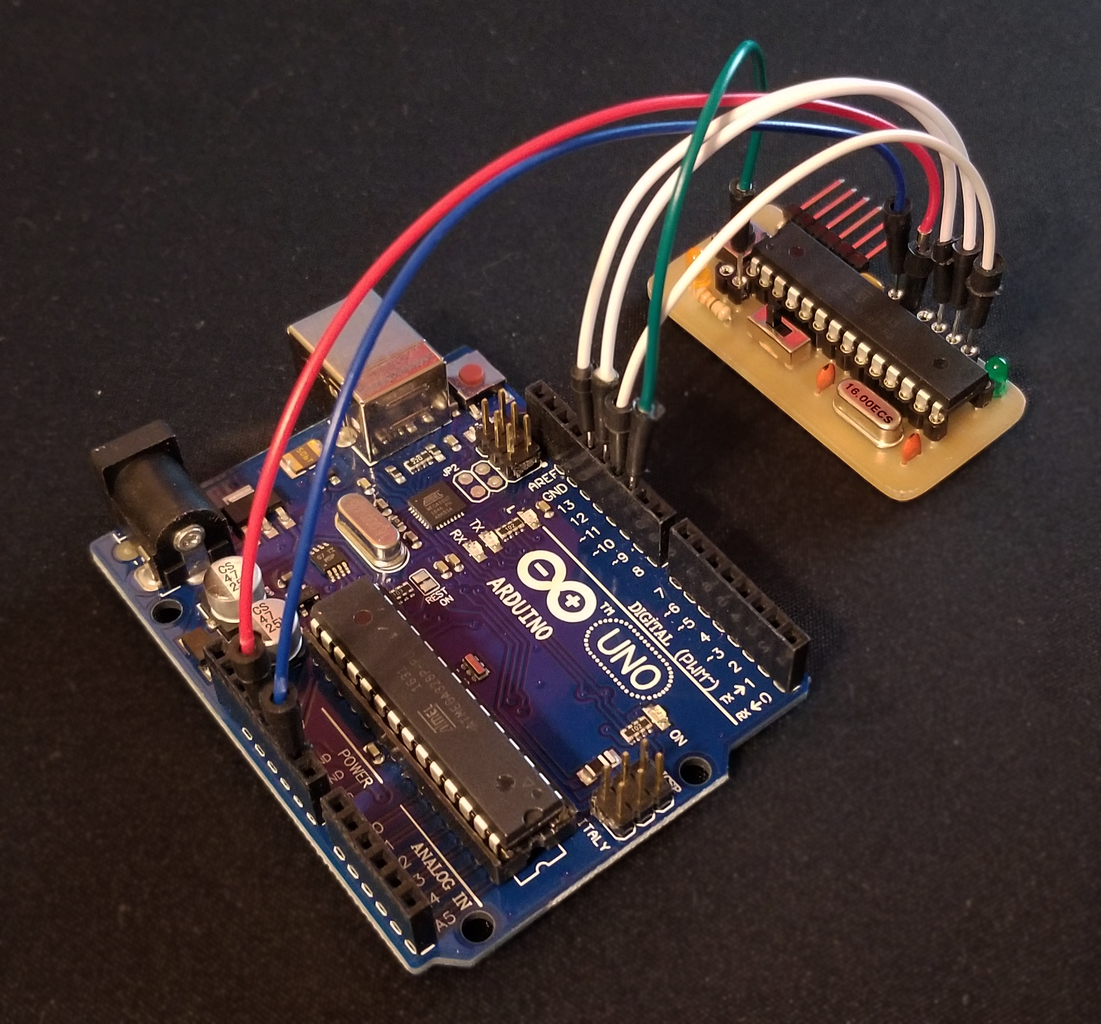
Wiring the Bootloader to the Companion Board:
[Bootloader Arduino] --> [Atmega328p Companion Board]
- D10 --> Reset / pin 1
- D11 --> MOSI / pin 17
- D12 --> MISO / pin 18
- D13 --> SCK / pin 19
- 5V --> Vcc / pin 20 or 21
- GND --> Gnd / pin 22
The pins refer to the legs of the IC itself. If this is confusing, look at the board picture from the schematic/layout step as the pins on the companion board are labeled.
Flashing the Bootloader:
Now that you've got the Bootloader Arduino setup with the optiLoader.ino sketch and it is also now wired to your Companion Board, ensure that the companion board switch is set to "bootload" instead of "upload", and then plug in your Arduino to a computer. You should see the lights on both your Arduino and Companion Board flash a number of times. After a few seconds, both should go dark and not flash anymore. This probably means that it's successfully flashed your atmega328p IC with the bootloader. To make sure that everything went well, plug it into your computer and open the Arduino IDE and then the serial monitor. Change the baud rate to 19200. Then, if it doesn't automatically restart, hit the reset button on your Arduino. You should see a bunch of text describing what the script is doing. At the end, it should not have any error messages and should inform you that the process is done.
If you do get an error, check your switch and make sure that you're on "bootload". If you're still getting errors at this point, check all your wiring and make sure that it's correct.
Step 5: Uploading

This is the easy step.
Disconnect all the wires from the previous step and flip the switch from "bootload" to "upload." Plug in your FTDI module. I like the Adafruit CP2104 and the SparkFun CH340G mainly because they're relatively cheap and the pinout matches the FTDI pins coming off of the companion board.
Once you have your FTDI plugged into your companion board, go ahead and plug it into your computer. From there, upload blink example sketch to make sure that the bootloader was flashed correctly. Select Arduino/Genuino Uno from the boards menu. Once the blink sketch is uploaded, you should see the blink LED blinking, as expected. If that works, then you're ready to use upload your own custom sketches to the IC, just as you would with any other Arduino.
Step 6: Future Work
In the future, I'm planning on making this into an Arduino Uno shield. It shouldn't take long to do so, and if people want, I can upload the Eagle files for that here as well. This would simplify the bootloading step, as you wouldn't need to worry about wiring it incorrectly. I'm open to other suggestions for improvement as well, however, I don't suspect I'll be doing a whole lot more with this, as it was just a necessary step in prepping my future projects.
If you want to see more of my future projects, let me know, and I'll try to keep the community posted.

Participated in the
First Time Author Contest 2018


