

Introduction: Atmel Startup 5: Lifeline


M. A. Parker c2015
The Lifeline is a simple circuit based on the Atmel ATTiny2313A microcontroller unit (MCU) that functions as a substitute clock source for a target MCU rendered inoperative by wrongly set clock fuses. The project, meant to be easy but useful for the expert, continues the series of ‘Startup’ Instructables [0] focusing on the individual Atmel Microcontroller MCU [1]. It makes use of the breadboard circuit from Blinky One (Startup 3) and the cable adapter from Startup 1 although both will be shown in brief for convenience. Working with the singlet MCU offers significantly lower cost for each project with much better control over the size, function and power requirements compared with the MCU-on-a-board systems such as Arduino [2] and the Rhaspberry Pi [3].
**NOTE: For those wanting the PDF of this instructable, download the attached PDF using the below link rather than the one automatically generated by the website - that automation does not maintain the association of the captions with the pictures.
Almost every time I program the fuses on an Atmel Microcontroller unit (MCU), I manage to wrongly set the clock fuse (SUT_CKSEL) which renders the MCU inoperative (i.e., bricked). What to do? The problem originates in choosing the wrong clock source for the actual hardware present or sometimes by choosing a clock division factor clk/8. Well, this article builds one of the simplest possible MCU circuits to help correct the problem – the Lifeline Mark I (Figure 1). It simply connects to a pin on the bricked MCU to supply a clock signal while the user reprograms the clock selection fuse (SUT_CKSEL) on that MCU. Do you know someone who has misprogrammed the clock fuses and then subsequently the person has added strange new curse words to the English language? Perhaps the Lifeline would be the perfect low cost gift!
The Lifeline uses a single Atmel AVR MCU [1], rather than the larger and more expensive Arduinos [2]. With the single Atmel MCUs, the builder controls all the options. There are smaller ATTiny MCUs but the 2313A has great capabilities in terms of pins, memory and functions; consequently, the Lifeline can be expanded for testing other MCU functions such as the serial port. And while Raspberry PIs [3] are remarkably capable of running Linux with plenty of USB peripherals, these PIs with Linux are event driven and consequently do not run in real time very well.
As mentioned, the solution to the problem of wrongly set clock fuses consists of simply setting up another circuit with the proper frequency and amplitude. The solution described here consists of using the Atmel ATTINY2313A MCU clocked by the internal 8MHz oscillator which, under programmatic control, drives a port pin at about 1.5MHz which, in turn, drives the dead-MCU pin intended for the crystal. The Lifeline (Figure 1) is built into a battery holder with a switch that was originally built to hold four AA cells but now holds three cells and the ATTiny2313A. Target MCUs operating at lower voltage can be accommodated by removing one cell and shorting the corresponding contacts together in the enclosure or adding a resistor to the Lifeline output. One can easily extend the function of the Lifeline to include basic testing of other MCU functions such as the serial port and ADC by adding some programming to the MCU and bringing a couple more wires outside the enclosure.
The Lifeline Mark I does not reset other fuses that might have been wrongly set. Certain ones such as RESET and SPIEN can render the Atmel MCU inoperable. In such a case, the fix requires a 12V (i.e., ‘high voltage’) programmer which can be built [4] or purchased from Atmel.
The Lifeline requires three constructions including the (i) enclosure, (ii) programmer cable adapter, and (iii) experimenter’s breadboard circuit. The programmer cable adapter was constructed in Startup 1 and the breadboard circuit was constructed in Startup 3; however, brief construction details will be included for both in step 4.
Attachments

Step 1: Construction of the Lifeline Enclosure

Figure 2: Plastic retainer (on the right side) and the lower rear contact have been removed. The switch can be seen attached to the holder on the upper right. Figure 3: The spring was pulled off of the electrical contact and the contact was then filed to roughen the surface, and finally, a wire was soldered to the contact. The contact can then be replaced into the plastic holder by pressing it straight down in the slots. Figure 4: The original red wire is soldered to IC Pin 12 (lower right). One end of a wire is soldered to the lower left contact and the other end to MCU Pin 20. Another wire has one end soldered to IC Pin 10 and its other end to a terminal on the switch (which also has a black wire). Note that Pin 1 is near a small notch at the end of the socket. Figure 1B: Repeat of finished case for comparison.
The Lifeline housing modifies a switched battery holder capable of holding four AA batteries. The modifications and additions to the enclosure are relatively straight forward and easy. The prototype described here uses three AA batteries that can produce voltages to approximately 4.9 volts. As such, the Lifeline should only be used with target MCUs running off 5V. Steps 2 and 3 below provide alternatives for those target MCUs operating on 3.3 volts but for the Lifeline Mark 1, we prefer to add a 1000 Ohm series resistor or replace one battery with a shorting screw to cover various possible scenarios. The following steps provide the modifications to the enclosure:
The first step for constructing the Lifeline consists of opening the enclosure and gently prying up the plastic retainer above the switch starting at one end rather than in the middle (Figure 2). However, damaging the retainer doesn’t cause much problem since it doesn’t add much strength to the box.
Pull out the metal contact with the red wire from the plastic case using pointed-nose pliers – the contact pulls straight up. Clip off the red wire at the contact but leave it positioned through the right-hand hole in the plastic case. The red wire will be connected to MCU pin 12 for the output signal. Notice pin 12 refers to the 20pin DIP package for the ATTiny2313A. See Figure 2.
Remove the contact set furthest from the switch using pointed-nose pliers – it pulls straight up. Refer to Figure 2. Pull off the spring. Use a fine file to file/roughen the portion of the contact where the spring was attached. Using a third hand to hold the metal, heat the metal with a soldering iron and flow solder until the hole has filled. See Figure 3.
Solder thin 24ga copper wire (stranded is better but solid will work) to the contact in such a manner that the wire will be on the inside of the enclosure when the contact is replaced (Fig. 4) rather than being located between the metal and the plastic. The wire is red to indicate that it will be the positive connection to the battery. Solder the other end to pin 20 on the dip socket. Replace the contact in its socket. Figure 4 shows the batteries and the MCU in its socket, which has been placed upside down in the battery holder so that the pins are visible.
The IC socket is already connected to the positive battery contact. We need to connect the battery negative to the IC socket but through the switch. Notice that the switch has a black wire soldered to one terminal and the negative battery contact is soldered directly to the middle switch terminal. So, solder a 24ga wire (stranded is better but solid will work ok) to the black lead on the switch and solder the other end to pin 10 as shown in Figure 4. The black lead leaving the plastic enclose will be the logic ground and it will be connected to the logic ground of the external circuit. The switch breaks the ground connection to the battery and not the positive connection as is customary for many circuits.
The red wire that was previously connected to the metal contact in item 2 above can now be attached. Solder the end of the red wire to pin 12 on the dip socket. Wrap the red wire around the plastic post for a little extra support and then pass it through the case hole.
Push the dip pins down making sure they don’t short. If you don’t anticipate adding more function (and hence wires), you can add some quick drying epoxy to secure the pins. Do not install the MCU as that needs to be programmed using an experimenter’s board.
Replace the plastic retainer and you are done with this section unless you plan to use Lifeline with 3.3V Atmel MCUs in which case continue reading.
If you anticipate working with AVRs biased at 3.3V, then some alterations should be made since the Lifeline running with the three batteries could damage the target AVRs. The Atmel MCUs have diodes connected to the pins (Startup 4) that can help protect the MCU but these diodes can only handle about 1mA. There are several possible solutions: (1) Remove one of the batteries and short the enclosure’s contacts for the removed cell. (2) Add a 1000 Ohm resistor in series with the output wire (red) from pin 12. (3) Add another switch or other components. We implement options 1 and 2 when necessary – both have been tested and work OK. In fact, the three-battery Lineline with the series resistor can safely reprogram bricked AVRs built on experimenter’s breadboards and running on either 5V or 3.3V. It might seem like a good idea to permanently add the resistor inside the enclosure since it will work with both voltages, but that resistor will also reduce the drive current to the pins of the targeted bricked MCU especially when other components might be connected to those pins.
Step 2: Option: Add a Series Resistor When Needed

Figure 5: A 1000 Ohm resistor is clipped to the red wire (connected to pin 12 inside).
This is the easiest of the additions. Figure 5 shows the 1000 Ohm resistor clipped to the red output wire (MCU pin 12). If the bricked MCU is on an experimenter’s board, then the 1000 Ohm resistor can simply be added to the board with the Red wire connected to one end of the resistor. If preferred, the resistor can be attached to the red lead using alligator clips or even soldering it (but it’s a pain to remove it when soldered). This approach works very well for MCUs on experimenter breadboards regardless of whether the target bricked MCU runs off 5V or 3.3V. In other words, if a person only works with MCUs on experimenter’s boards, then the 1000 Ohm resistor could be placed between pin 12 and the red wire inside the Lifeline enclosure.
Step 3: Option: Remove a Battery and Short the Terminals With a Screw

Figure 6: Left: The 8-32 screw positioned into the screw cutter. Right: Two nuts have been added to the screw to help stabilize the screw once installed. Figure 7: A battery has been removed from the Lifeline and the cut screw has been inserted. The screw head presses against the spring on right and the threaded end fits into a slot at the negative contact. Figure 1C: Repeat of finished case for comparison.
This approach requires some more construction but has the advantage of allowing the Lifeline better drive capabilities to the target bricked MCU, which doesn’t need to be on an experimenter’s board.
Obtain an 8-32 round-head screw with thread length of 1.5 inches and two 8-32 nuts. If only a longer 8-32 screw can be found, such as 2 inches, then proceed to Item 2 and cut the screw. If you found a screw with 1.5 inch long threaded section, then procedure to Item 3.
Use a screw cutter to trim the screw to the thread length of 1.5 to 1 9/16 inches. Figure 6 shows the screw positioned in the screw cutter (from Home Depot). Some people cut the screws using hacksaws or Dremel tools. Once cut, the threads might need to be shaped by using needle files or re-threaded using a 8-32 die.
Place two 8-32 nuts on the end of the cut screw as shown in the right side of Figure 6. The nuts will help stabilize the screw in the battery compartment. Notice that about 1/4 inches of thread remain on the right side in order for that end to properly fit the contact. Tighten the nuts against each other. The head of the screw will be placed against the spring.
Install the screw in the battery compartment when needed. The head of the screw presses against the spring and the threaded end presses into the negative contact (Figure 7). The back can be replaced on the enclosure.
As previously mentioned, the screw or resistor should only be used when the need arises for programming a 3.3 V atmel MCU.
Step 4: Review of the Circuit and Adapter Cable

Figure 8: Schematic diagram of the circuit.
By this point, the breadboard circuit and the adapter cable should have been constructed. This step provides brief instructions. Full details [0] can be found in Startups 1 and 3.
Make sure the breadboard circuit has been connected as shown in Figure 8. Be careful that the 9v battery positive terminal connects to the regulator input and NOT the 5v rail at the top of the breadboard. Keep in mind: do not reverse bias the MCU (or else kaput), do not reverse bias the capacitor (or else stinky kaput), do not reverse bias the LED (or else maybe nothing). The capacitors and resistors either have the value printed on the side or else they have codes as shown in References [5,6]. For the LED, choose Red or Green for use with the 2.2k resistor shown in the schematic. Blue will be ok but you might want to change the resistor to 1.5k to make it brighter.
The adapter appears at the top of Figure 8. It is constructed using a piece of double row male header available from Amazon.com for example. Clip off a piece of the header so as to have 2 rows, 3 columns. Solder 6-inch 24guage plastic-coated solid wires to the short side of the pins per Figure 8. Apply quick dry epoxy to the side of the header with the short pins being sure to cover part of the wires (no more than about 1/4 inch and being careful not to put any epoxy on the longer side of the pins. Label the wires according to Figure 8 in this text.
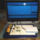
Step 5: Create the Lifeline Solution If Not Previously Created
This Step should be skipped if the Lifeline solution was previously created in Startup 2 or 3. The abbreviated procedure appears below.
1. Connect the programmer to the USB port and start Atmel Studio 6 (AS6).
2. Click the menu sequence Files > New Project. Choose C++Executable.
3. Next to ‘name’ type ‘Atmel Lifeline’. Check the box next to ‘Create Directory for Solution’.
4. The Device Selection Dialog pops up. Select ‘ATTiny 2313A’. Click OK.
5. Select the Atmel menu sequence: Project > Atmel Lifeline Properites.
Select the left hand Device tab and verify Device = ATTiny2313A
Select the Tool tab and Select your programmer. The ISP Clock of 125 kHz will work – this value must match the one set in Tools > Device Programming. It must be less that ¼ of the clock rate of the MCU to be programmed.
6. Connect the 9V battery to the experiment’s board circuit and connect the programmer to the board through the adapter cable previously constructed.
7. Select the Atmel menu sequence: Tools > Device Programming. Verify that the Tool box displays your programmer and the device box displays ATTiny2313A, and the acronym ISP should appear in the 3rd box. Read the Target Volts – it should be within a few percent of 5V. Set the ISP Clock to 125 kHz to match that in Item 5 above.
8. Save and close the solution. Note: The full solution can be saved by clicking the icon with the multiple disks in the tool bar or else use File > Save All.
Step 6: Open the Existing Lifeline Solution and Set-up
As mentioned in previous Startups, the Atmel Studio AS bundles the various program files to form a Solution rather than a program. Open the existing Atmel Lifeline solution as follows. It’s a good idea to follow this procedure when opening any existing solution (except we don’t mess with the fuses once they have been set).
1. Connect the programmer to the USB port and attach it to the experimenter’s breadboard through the cable adapter constructed in Startup #1 (see also the parts list for brief construction). Connect the battery to the 9v batter clip.
2. Start Atmel Studio. Open Lifeline using the menu sequence:
File > Recent Projects and Solutions > Atmel Lifeline.atsln
3. Select the Atmel menu sequence: Project > Atmel Lifeline Properites.
Select the left hand Device tab and verify Device = ATTiny2313A
Select the Tool tab and verify your programmer. The ISP Clock of 125 kHz will work – this value must match the one set in Tools > Device Programming. It must be less that ¼ of the clock rate of the MCU to be programmed.
4. Select the Atmel menu sequence: Tools > Device Programming. Verify the Tool box names your programmer and the device box names ATTiny2313A, and the 3 rd box should show ‘ISP’. Click the APPLY button. If AS wants to upgrade the programmer firmware then go ahead and do it. If an error occurs then refer back to Startup#1 [0]. Next, read the Target Volts – it should be within a few percent of 5V. Set the ISP Clock to 125 kHz to match that in Item 5 above. Do not close the dialog – proceed to Item 5 below.
5. If the fuses have not been set for the current ATTiny2313A, then verify the following settings by clicking the fuses tab on the left. Refer to Startup #2 for details. Caution Caution Caution: Do not unnecessarily play with the fuses! And definitely don’t look cross-eyed at the ‘Lock Bits’ at this time – they are used to prevent the viewing of flash content – different MCUs have different lock bits.
SELFPRGEN : No Check; DWEN: No Check; EESAVE: No Check;
SPIEN: Checked; WDTON: No Check; BODLEVEL : Disabled;
RSTDSBL: No Check; CKDIV8: No Check; CKOUT: No Check;
SUT_CKSEL : INTRCOSC_8MHz_14CK_0MS
6. Close the dialog for Tools > Device Programming. Do not close the Atmel Studio (etc.).
Step 7: The LIFELINE One Program
The LifeLine program switches the ATTiny2313A B0 pin, which is physical pin #12 for the DIP package, at the fastest rate using the 8MHz internal clock with fairly symmetric waveform (i.e., square wave at 50% duty cycle). The Lifeline is simpler than the Blinkies discussed above. LifeLine Two provides some infrastructure for when the program might be extended to include other functions.
1. If necessary complete Step 6. Bring the file ‘Atmel Lifeline.cpp’ to the forefront by either double clicking the file in the AS Solution Explorer on the right hand side, or if visible, click the tab (under the AS menu) with the name ‘Atmel Lifeline.cpp’.
2. Remove any existing code and any ‘#define’ or ‘#include’ statements except for ‘#include <avr/io.h>. The new program should be entered exactly as below being careful to observe capitalization, semicolons, parentheses and braces.
#include <avr/io.h>
int main(void)
{
DDRB = 0b00000001; // or 0x01; Sets B0 as output and the rest as input
while(1)
{
// Three to symmetrize waveform
PORTB = 0x01; // LED ON
PORTB = 0x01;
PORTB = 0x01;
PORTB = 0x00; // LED OFF
}
}
3. Go ahead and compile Lifeline and load it into the MCU as described in Startup #3, Step 7. In brief, Press F5 or click the small triangle on the tool bar with the drop down box for Debug (not the one with the two vertical bars). If there are any errors or warnings, then correct them and try again.
4. At this point, the LED should have a dim glow somewhere between fully ‘on’ and fully ‘off’. That is, the emitted optical power should be between max and min (Pmax and Pmin as described in Startup 3, Step 8). If you modify the program by removing some of the PORTB = 0x01 statements, then you should be able to see different brightness for the LED.
5. Finally, remove the programmer from the USB port, disconnect the 9V battery from the experimenter’s board – the MCU is now ready to be inserted into the socket in the plastic enclosure constructed in Step 1.
Step 8: Meaning of the Lifeline One Statements

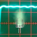
Figure 9: Photos of an oscilloscope display. Left: An unsymmetrical waveform from Pin 12 when using only one PORTB = 0x01 statement in the Lifeline program. Right: A symmetrical waveform using the three PORTB = 0x01 statements. The horizontal scales differ between the left and right side by a factor of five; however, Pin 12 spends the same length of time in the zero state for both the left and right side.
The programming statements have the following meanings [7-13]. Expanded discussions can be found in Blinky One and Two (Startup 3, 4). Note that three statements of PORTB=0x01 have been used compared with the single statement of PORTB = 0x00 in order for pin #12 on the ATTiny2313A (DIP package) to spend the same amount of time at Vcc as it does at 0volts (i.e., 50% duty cycle to produce a square wave) – see Figure 9 for an example. The figure shows the frequency is approximately 1.5MHz. The extra statements of PORTB=0x01 do not affect anything but add delay.
#include <avr/io.h>: Includes io.h header file which includes other .h files for the specific MCU [14]. These other .h files define keywords such as DDRB, PORTB, PB0, TIMSK, and TCNT0. Not viewed with the ‘go to implementation’.
DDRB = 0b00000001: Sets PortB pins to all function as inputs except for B0 which is an output for the MCU.
while(1) : Continuously executes the statements contained within the following braces { } since 1, which is another name for ‘true’, is always true.
PORTB = 0x01: Sets the B0 output bit to 1 which the MCU circuitry converts to Vcc on pin #12 (for the DIP package of the ATTiny2313A). The LED illuminates. Keep in mind that this command also sets B1-B7 to zero which can affect pull-up resistors or physical pins depending on the bits in DDRB – in this case, it disables the pull-up resistors since zero is written to an input.
PORTB = 0x00: Sets all of the bits in B to zero. The LED extinguishes. Keep in mind that this command also sets B1-B7 to zero which can affect pull-up resistors or physical pins depending on the bits in DDRB.
Step 9: The LIFELINE TWO Program
The Lifeline Two program is intended for those planning to modify the Lifeline to make it suitable for testing other functions of other MCUs. This second program modifies the PORTB commands so that the ‘writes’ using ‘PORTB=’ will not affect other output pins and pull-up resistors associated with inputs (somewhat similar to Blinky Two).
1. If necessary repeat Step 6. Bring the file ‘Atmel Lifeline.cpp’ to the forefront by either double clicking the file in the AS Solution Explorer on the right hand side, or if visible, click the tab (under the AS menu) with the name ‘Atmel Lifeline.cpp’.
2. Remove any existing code and any ‘#define’ or ‘#include’ statements except for ‘#include <avr/io.h>. The new program should be entered exactly as below being careful to observe capitalization, semicolons, parentheses and braces.
#include <avr/io.h>
int main(void)
{
DDRB = 0b00000001; // or 0x01; Sets B0 as output and the rest as input
while(1)
{
// Two to symmetrize waveform
PORTB |= 0x01; // Mask = 0x01
PORTB |= 0x01;
PORTB &= ~0x01;
}
}
3. Go ahead and compile Lifeline Two and load it into the MCU by pressing F5 (See Step 7, Item 3).
4. At this point, the LED should have a dim glow somewhere between fully ‘on’ and fully ‘off’. Refer to Startup 3, Step 8 for more discussion if interested [0].
5. Finally, remove the programmer from the USB port, disconnect the 9V battery from the experimenter’s board – the MCU is now ready to be inserted into the socket in the plastic enclosure constructed in Step 1.
Step 10: Meaning of the Lifeline Two Statements
The programming statements have the following meanings [7-13]. Expanded discussions can be found in Blinky Two, Startup 4. Note that two statements of PORTB |= 0x01 have been used compared with the single statement of PORTB &= ~0x00 from Lifeline 1 in order for pin #12 to dwell equal times at Vcc and 0v (i.e., 50% duty cycle to produce a square wave) with frequency of approximately 1.0 MHz. The extra statement of PORTB |= 0x01 does not affect anything but adds delay.
#include <avr/io.h>: IO.h includes other header files (i.e., having the .h extensions) for the specific MCU [14] These other .h files define keywords such as DDRB, PORTB, PB0, TIMSK, and TCNT0. Cannot view with the ‘go to implementation’.
DDRB = 0b00000001: Sets PortB to all inputs except for B0 which is an output for the MCU.
while(1) : Continuously executes the statements contained within the following braces { } since 1, which is another name for ‘true’, is always true.
PORTB |= 0x01: Shortcut notation for PORTB = PORTB | 0b00000001 where the symbol | refers to the bitwise OR discussed in Startups 3, 4. The statement sets the B0 output bit to 1 which the MCU circuitry converts to Vcc on pin #12 (for the DIP package of the ATTiny2313A). The LED illuminates. The statement only affects bit B0 and so the output state and pull-up resistors for the other bits in the B register remain unchanged.
PORTB &= ~0x01: Shortcut notation for PORTB = PORTB & ~0x01 where the symbol & is the bitwise AND operator and the symbol ~ is bitwise negation. For discussion, see Startup 4. Because ~0x01 = 0b11111110, bit B0 is forced to be zero and so the MCU circuitry sets the ATTiny 2313A (DIP package) pin #12 to 0volts, which extinguishes the LED. The 1s in the other bits of 0b11111110 and the use of AND means that the other bits in PortB B1-B7 do not change so the output pins do not change state nor do the pull-up resistors.
Step 11: Using the LIFELINE Module
Once the LifeLine has been programmed using the experimenter’s board circuit, the ATTiny 2313A (20 pin DIP package) can be placed in the socket in the plastic case constructed in Step 1. Make sure to align IC pin 1 with the socket pin 1. That is, make sure that pin 10 on the MCU will be connected to ground (battery negative) and pin 20 will be connected to Vcc (battery positive). Close up the enclosure.
One hopes that the Lifeline won’t be needed but accidents do happen. Assume that you have a ‘bricked’ (i.e., dead) MCU because of wrong settings for CKDIV8 or SUT_CKSEL. In such a case, proceed as follows:
Make sure the Lifeline has been switched to OFF
Make sure that your Lifeline has compatible voltages with your bricked MCU. A Lifeline with 3 batteries can be used with a bricked MCU with a 5V supply but it should not be used with a bricked MCU running on 3.3V. If the voltage level of the bricked MCU is too low, the Lifeline will damage it. Often ICs will include protection diodes such as described in Startup 4. But the Atmel MCU diodes will not protect against more than about 1mA. Refer to Step 2 and 3 on the modifications to the Lifeline circuit for bricked MCUs with various supply voltages.
Attach the negative wire from Lifeline (black) to the bricked MCU’s ground. Make sure this is the negative lead as otherwise the MCU can be damaged.
Locate the crystal connections on the MCU. For example, as described in the specification document for the ATTiny2313A http://www.atmel.com/Images/doc8246.pdf, the crystal would be attached to pins 4 and 5. So far, I have only reset the clock-related fuses without the crystal in the circuit (and without an external RC attached to those pins). If you have a crystal soldered into a board holding the bricked MCU, you can try the following procedure but you might need to remove the crystal.
Attach the red wire from the Lifeline to one of the identified crystal pins of the bricked MCU. If the following procedure does not properly work then attach the lifeline red wire to the other crystal pin and try again. I usually start with the pin having the higher number (such as #5 for the ATTiny2313A). Make sure that you attach the red wire (i.e., the wire attached to the Lifeline MCU pin 12).
Connect a programmer to the bricked MCU and the computer. Start Atmel Studio (AS6). You might find it convenient/necessary to open the AS6 program that caused the malfunction in the first place.
Turn on the Lifeline power switch
Along the top AS6 menu, open Tools > Device Programming. Your programmer should be listed along with the name-number of the bricked MCU.
Click ‘Fuses’ on the left hand side of the dialog. You should be able to see the wrongly set fuses.
Correct the clock-related fuse settings.
Shut down Lifeline and remove the programmer and you should be good to go.
Step 12: Parts List
The parts should already have been accumulated in previous startups. However, the list is repeated here in brief for convenience.
Atmel Programmer: ATATMEL-ICE-BASIC at Mouser.com or Digikey.com for about $55.
Atmel Studio AS6 (free): http://www.atmel.com/tools/atmelstudio.aspx
ATTiny 2313A: Digikey.com ATTINY2313A-PU-ND at $1.70 (pDIP package, 20pins).
Startup #5: 20 pin socket for DIP package (0.3” row spacing, 0.1” pin spacing), low profile: Digikey.com ED3054-5-ND or AE9998-ND for about 30cents. Similar sockets can be found on Amazon.com.
LM7805 Regulator: Digikey.com LM7805CT-ND or LM7806ACT-ND for about 70Cents.
Electrolytic Capacitor 10uF, 50V: A large variety of capacitors but aluminum type will work ok:
Digikey.com: P997-ND (mfr. number: Panasonic ECE-A1HKS100) about 30cents. Actually Amazon has a capacitor kit with both ceramic and electrolytic for $20 called “Joe Knows Electronics 33 Value 645 Piece Capacitor Kit” which looks like a reasonable set.
Ceramic Capacitor 0.1uF 50V: Again, a large variety available here. Digikey.com 399-4454-1-ND (Kemet C410C104M5U5TA7200) for about 25cents. See also the kit listed in #7 above.
Optional: Two Ceramic Capacitors 22pF (25-100V ok) such as Digikey.com 490-8663-ND at 34 cents.
Optional: Purchase a crystal from the HC-49US series or a series with a similar profile. Capacitance loads in the range 18-22pF more or less and less than about 50 Ohm equivalent series resistance ESR will work ok. Amazon has nice packages of crystals as found by searching Amazon for 16MHz Crystal or 8MHz Crystal etc. Here are some from Digikey.com:
16MHz Crystal from Digikey 300-6034-ND at 54cents each.
20MHz Crystal from Digikey 300-6042-ND at 54cents each.
8MHz:
8MHz Crystal from Digikey X164-ND or X1093-ND at 81cents each (but ESR=80).
8MHz Crystal from Digikey X100-ND 70cents each (but larger profile)
Amazon.com: Search 8MHz Crystal – good selection, low profile, good ESR
10MHz Crystal from Digikey 887-1010-ND at 33 cents each.
LED: Amazon has a package of 50 LEDs of various colors for $10 (see Microtivity IL 185). Ebay has many.
Resistor: Search Amazon.com for ‘resistor kit’. The SparkFun 500 1/4W resistor kit and the E-Projects – 400 Piece, 16 Value resistor kit look OK. Here are the values listed for Digikey:
1K Digikey.com: CF14JT1K00CT-ND 10cents each
1.5k Digikey.com: CF14JT1K50CT-ND 10cents each
2.2k Digikey.com: CF14JT2K20CT-ND 10cents each
2.7k Digikey.com: CF14JT2K70CT-ND 10cents each
3.3k Digikey.com: CF14JT3K30CT-ND 10cents each
4.7k Digikey.com: CF14JT4K70CT-ND 10cents each
5.6k Digikey.com: CF14JT5K60CT-ND 10cents each
Resistor 10k required for the RST and 1k for using Lifeline with 3.3V.
1k Digikey.com: CF14JT1K00CT-ND 10cents each
10k Digikey.com: CF14JT10K0CT-ND 10cents each
Optional for Startup #4: Photo-transistor. Order from either Digikey.com or Amazon.com
Digikey: Everlight PT334-6C 38cents each
Amazon: Search ‘Everlight PT334-6C’ about $5 for ten.
Optional for Startup #4: Photo-resistor from Amazon. Just about any will work ok.
Amazon.com search for ‘photoresistor GM5539’. Cost $5 for ten.
Digikey PDV-P8001-ND by Advanced Photonics mfg # PDV-P8001 for $2.22
9v Battery clip: Radio Shack or search amazon.com for ‘9v battery clip’ (10 for $2).
Digikey.com: BS6I-ND 60 cents.
The plastic housing for the Lifeline is constructed from a battery holder for 4 AA batteries that also has a switch. These come from Radio Shack or Amazon.com. For amazon, search for ‘plastic battery holder 4 AA switch’. Make sure the case holds 4 AA batteries and has a switch. I found a deal of five cases for $8.
Experimenter’s breadboard: There are many types and sizes and places to purchase.
Amazon.com: MB-102 Point Prototype PCB breadboard for $5 includes wires
Amazon.com: MB-102 830 Solderless Breadboard for $4 with wires. 8-32 screw 1.5” long.
Screw 8-32, 1.5inches long: check HomeDepot.com or Lowes.com. Any 8-32” screw longer than 2” will be ok so long as it is later cut to a length of 1.5”. You need two 8-32 nuts. Many times the 8-32 screws come with either a large flat head (truss head) or the smaller round heads (round head). Find the round head since these fit better with the spring. The truss head would likely need to be filed down.
24 gauge solid core copper wire. 0ld telephone/intercom wire and intercom wire will work and has many colors. The 24ga has a diameter of approximately 0.51 mm but it’s not critical. Amazon.com: search on ‘4 conductor 24 awg cable solid copper’ either 60cents/foot or $20 for 100 feet. Ebay.com has nice 24 ga. solid core wire with multicolors. Search: ‘solid 24 gauge wire kit’. Home Depot: 100 ft. 6-conductor Indoor Phone wire for $20. For soldering the ICs and components, you might want to use 24ga stranded copper wire since it is more flexible and less likely to pull loose from the joint. Amazon.com: search for ‘24 gauge stranded wire’. Nice 6 spool kits (150’ total) will come up for $20.
Step 13: References
[0] The Atmel Startup articles, Instructables.com, 2015, M. A. Parker, Angstrom Logic:
A. Atmel Startup 1: Atmel Studio and Programmer
B. Atmel Startup 2: Microcontroller Circuits and Fuses
C. Atmel Startup 3: Blinky One – PORT, PIN, DDR and LED
D. Atmel Startup 4: Blinky Two – Switches, Pull-Up Resistor, and Bit Ops
E. Atmel Startup 5: Lifeline
As a note, these Instructables made extensive use of the free HTML conversion tool at
by cutting and pasting into the tool and then cutting and pasting the results into the Instructables page using the HTML view.
[1] The complete Atmel manual for the ATTiny 2313A: http://www.atmel.com/Images/doc8246.pdf.
More information on the ATTiny2313A can be found at
http://www.atmel.com/devices/ATTiny2313A.aspx .
[2] Arduino products and learning: http://www.arduino.cc/
[3] Raspberry Pi products and learning: https://www.raspberrypi.org/
[4] Fix big problems with fuses: DIY 12V Programmers (i.e., ‘High Voltage’)
https://sites.google.com/site/wayneholder/attiny-fuse-reset http://www.rickety.us/2010/03/arduino-avr-high-voltage-serial-programmer/
http://mightyohm.com/blog/2008/09/arduino-based-avr-high-voltage-programmer/
https://www.instructables.com/id/AVR-Attiny-fusebit-doctor-HVSP/http://www.societyofrobots.com/member_tutorials/book/export/html/239
[5] Capacitor codes: http://www.wikihow.com/Read-a-Capacitor
[6] Resistor color code https://en.wikipedia.org/?title=Electronic_color_code
[7] The classic masterpiece: B.W. Kernighan, D. M. Ritchie, “The C Programming Language”, Prentice, 2nd Ed. (1988). Available on amazon.com for $7.
[8] Good C++ review after reading the Kerninghan-Ritchie book and some background in OOP. “C++ Super Review” written by The Staff of Research and Education Association, published by Research and Education Associated (2000). ISBN: 0878911812. Amazon.com for $8.
[9] A good C++ tutorial site can be found at http://www.cprogramming.com/tutorial.html#c++tutorial
[10] Good overview of Atmel concepts and C but uses the AVR Butterfly:
J. Pardue, “C Programming for Microcontrollers Featuring ATMEL’s AVR Butterfly and the free WinAVR Compiler”, Published by Smiley Micros (2005). ISBN: 0976682206. Amazon.com
[11] Keep in mind that avrfreaks.net has tutorials and project help
http://www.avrfreaks.net/forum/newbie-start-here?name=PNphpBB2&file=viewtopic&t=70673
http://www.avrfreaks.net/forums/tutorials?name=PNphpBB2&file=viewforum&f=11
[12] SparkFun website has a variety of tutorials ranging from electronics to software:
https://learn.sparkfun.com/tutorials/tags/concepts.
And a blinky here: https://www.newbiehack.com/MicrocontrollerTutorial.aspx.
[13] GCC reference:
http://www.gnu.org/software/gnu-c-manual/gnu-c-manual.pdf
https://gcc.gnu.org/onlinedocs/
https://gcc.gnu.org/onlinedocs/libstdc++/
[14] Content of avr/io.h: http://www.nongnu.org/avr-libc/user-manual/io_8h_source.html


