

Introduction: Attiny85 Programming (shield) Using Arduino UNO


Playing with your Arduino is great fun. However, sometimes size does matter.
The Arduino UNO is small, but if you require your project to be in a small enclosure, the UNO might be way too big. You could try using a NANO or MINI, but if you really want to go small, you go tiny, Attiny to be precise.
They are quite small, cheap chips (basically small Arduinos) and can be programmed in the Arduino IDE, however you might notice that there is no USB connection. So how do we program it???
For every problem, there is a solution. You can easily make your Arduino UNO into a programmer, connect it with the Attiny and program it that way.
Now, if you do it once, that's a good option, however if you get into playing with your Attiny, you might notice that connecting all those wires over and over again gets pretty annoying.
If only there were some way we could just connect the Attiny to the Arduino without having to use a breadboard and all those wires. And there is!
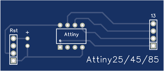
In this insturcable I will show you how to make your very own Arduino Attiny shield, that works with Attiny25/45/85.
You can either make it on a breadboard (which looks quite messy) or you can use a PCB.
BTW, this Instructable is entered into the PCB Contest, so if you liked this Instructable, consider giving it your vote at the end of the Instructable.
Step 1: What You'll Need
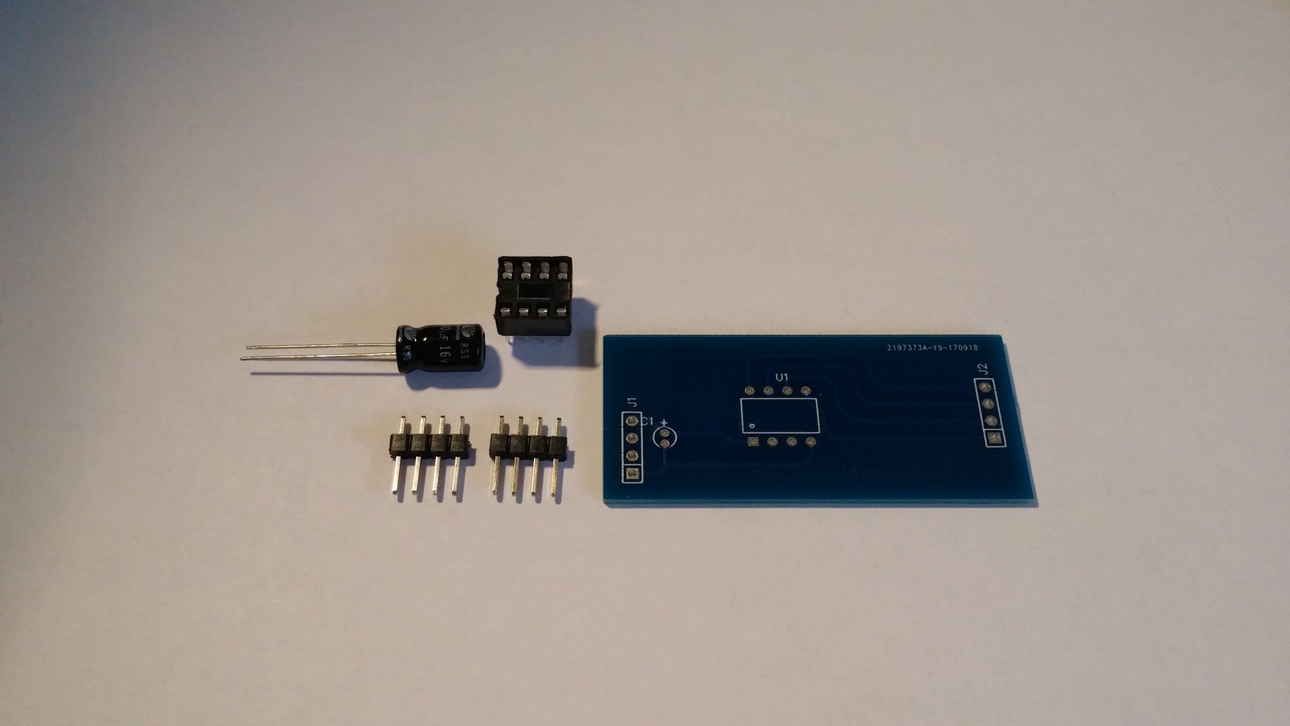
For this project you will require:
-Arduino IDE (a newer version is recommended, but anything 1.6.x or newer should work)
-Attiny25/45/85 (you don't actually need it to make the programmer, but there's no point in making the programmer if you don't own a chip)
-2pcs 4pin male header (you can buy a row of 40 and carefully break 4 off)
-1 electrolytic capacitor (anywhere from 10uF to 100uF is fine)
-8pin socket (or you can use 2pcs of 4pin female headers)
-Arduino UNO (of course clones work just as well)
-1 pcb board that fits on the UNO (or a breadboard and some wires if you just want to test things out)
For those of you who want a more elegant solution in an even smaller package, I recommend ordering a pcb from JLCPCB (10pcs cost around 10usd with shipping included). You can find the gerber files in step 4.
If you don't know what those are...you don't really need to know, simply download the zip and drag it onto the JLCPCB site, then place an order. More about this in the next step.
The JLCPCB made shield fits straight onto your Arduino UNO, you only need to solder on the components and you've got a perfect, compact Attiny programmer of your own.
Step 2: Pinout and Connections
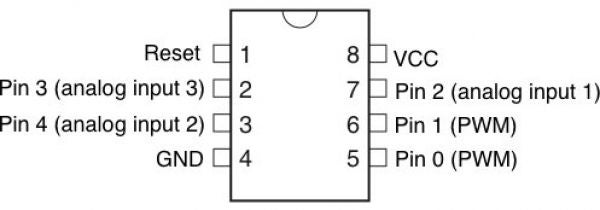

Here is a picture of the Attiny85 pinout. It is the same for the Attiny25
and Attiny45. Notice the small half circle at the top. Pay attention to it. It is there so you don't plug it into the circuit backwards by mistake.
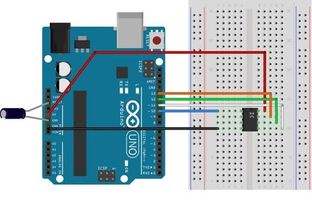
The half circle is represented by a small black dot on the chip (in the picture with the circuit connections)
For everyone else that's making the board from scratch, the connections should be as follows:
UNO------->Attiny
Pin 10----->Pin 1
Pin 11----->Pin 5
Pin 12----->Pin 6
Pin 13----->Pin 7
5V---------->Pin 8
Gnd-------->Pin 4
DO NOT FORGET to connect the capacitor between the Gnd and the reset pin on the Arduino UNO.
I recommend you put the male headers into the UNO's female headers, place the board on top so everything is as still as possible and then begin soldering so it will all fit later.
Once you've connected everything, check the connections again and the actual orientation of the Attiny. (remember the little dot on the chip)
If there are no mistakes, you can move on to the software part in step 4 or you can move onto step 3 and see how to order a professionally made PCB that looks way better and costs next to nothing.
Step 3: Making the PCB

You can either make your own PCB from according to the connections in the
next step or you can buy a proffessionally made one from JLCPCB. (Not a sponsor, but I wish they were)
Don't worry, you don't need to know what you're doing, just follow the pictures.
- First download the gerber files (zip file that's included in my instructable). Don't unzip it.
- Go to the JLCPCB website, here. https://jlcpcb.com/quote
- Drag and drop the ZIP file where it says "Add your gerber here" (as shown in the picture)
- There is no need to change the other options, so just click on "Save to cart"
- A new page will open, just slick "Checkout securely"
- On the next page, you'll need to fill in your shipping and payment info. I recommend you pay using paypal and using the cheap version of shipping (the express costs more but it should be at your doorstep in under 5 days), however the cheap one doesn't take that long either, around a couple of weeks.
- Click continue, pay for your boards and that's it. You'll get top quality made boards for next to nothing.
Now if you don't want to wait for JLCPCB to make and ship your boards or you just like getting your hands dirty and don't mind the end product looking messy, as long as it works, you can make your own board using a common stripboard by simply making the connections mentioned in step 3.

Step 4: Setting Up the IDE


The first thing you need to do is copy open up the Arduino IDE.
Go to File->Preferences
In the "Additional Boards Manager URLs:" paste this:
and click OK
Next go to Tools->Boards->Boards Manager (at the very top of the list)
In "Filter your search..." type attiny. It should only find one selection. Click on it and hit Install.
Once it's done installing, close the IDE so everything resets.
Congratulations! You have just finished the hard part, but you still need to prep your UNO to program the Attiny.
Step 5: Prepping the UNO for Programming

To program the Attiny, you have to (always) first upload a special sketch to
the UNO first.
You can find the sketch in File->Examples->ArdionoISP->ArduinoISP
Once that opens up, go to tools->Boards and select your UNO
Upload the sketch to it as you normally would.
Once that's done, your UNO has transformed into a programmer for the Attiny.
Go ahead and plug in the shield you've made in the previous steps, being careful to connect the correct pins and putting the Attiny in the right way!
Now on to actually uploading a program to the Attiny!
Step 6: Programming the Attiny


Open up the IDE again (hit File and click New) and go to Tools->Boards
If you scroll down, there you will find that you can now select the Attiny25/45/85 as a board.
Go ahead and select the Attiny25/45/85 option and now go back to Tools and in "Processor:" select which ever Attiny you intend to use.
But that's not all.
You also need to change the "Programmer" option to: Arduino as ISP (not ArduinoISP, be careful)
Now once that's done, you should be able to upload your code to the Attiny the same way as you would a regular Arduino.
Step 7: Additional Tips
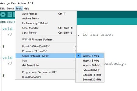
If you want to change the clock speed of the Attiny, you can do so by
clicking Tools->Internal X MHz and then clicking on Burn bootloader, while your Attiny is plugged into the UNO.
This will tell the Attiny to switch the clock speed to the speed you selected. (If you put in a delay of 1s and the actual delay is way shorter or way longer than that, you should probably try switching the clock speed)
Also when you'll want to take the Attiny out of the programmer, I recommend using some tweezers or something small and flat, so you can slip it under the Attiny and lift all the left and right side at the same time. That way you won't bend the pins when lifting it up.
If you enjoyed this Instructable, consider visiting my Fundrazr page here. And of course, share.

Participated in the
PCB Contest


