

Introduction: Audio Switcher (Arduino)


This project was came to a start because my school project group and I needed to switch multiple audio sources to one audio amplifier. When searching on the internet for some sort of audio switch module for Arduino we couldn't find anything like it. I already knew of a chip capable of switching analog signals, but no really useful mudules were available for it either. So I got to work and created my own.
Step 1: What Do You Need
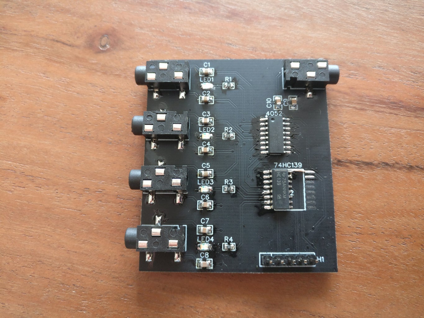
This board is completely SMD (except for the pin headers) which means all of the components are soldered on top of the PCB. This means the soldering connections are very tiny and thus harder to solder than through hole components. For this reason I recommend you not to try this without first practicing with larger components.
Bill Of Materials:
- 1x 74HC139
- 1x CD4052
- 10x 10uF capacitor (0805)(bipolar)
- 4x LED (0805)
- 4x 330 ohm resistor (0805)
- 5x female audio jack
- 1x 5 pin header
There also is a BOM exported from EasyEda:
Attachments

Step 2: The Schematic Explained

I will only go over the workings of the schematics briefly so most people can follow this if they want.
As the pin header is not that interesting we'll move on to the 4052 chip. This chip is a dual analog switcher and as the name implies it switches the audio signal from on of it's four inputs and directs it to the one output. Because most of the time audio is stereo we need two audio switchers. this is where the "dual" comes in handy. The lables are marked as CH1_L for "channel 1 left" or COM_L for "common left" and can be followed to the jack connectors.
Next up is the SN74HC139. This is a demultiplexer but don't worry about this weird term. Its main functionality is to indicate which channel is currenty selected to pass through the audio signal. This is the part where I made a minor mistake. It was supposed to light up an LED at the channel which is selected, but as it is it lights up all leds EXCEPT for the selected channel. So you can think of the LEDs as "this channel is muted" indicators.
The only parts left are the audio jack connectors. Nothing special to see here actually. The only thing that might seem weird is the capacitors. These are decoupling capacitors and they block DC signals and let trought AC signals like audio.
Step 3: Ordering a Board

As you may have seen on the photos of the real PCB I had to make a connection with a wire which I didn't plan for. This is because the package of the 74HC139 is not correct (an error of the EasyEda library).
This mistake has not been fixed so keep this in mind when ordering!
Attachments
Step 4: Using the Board
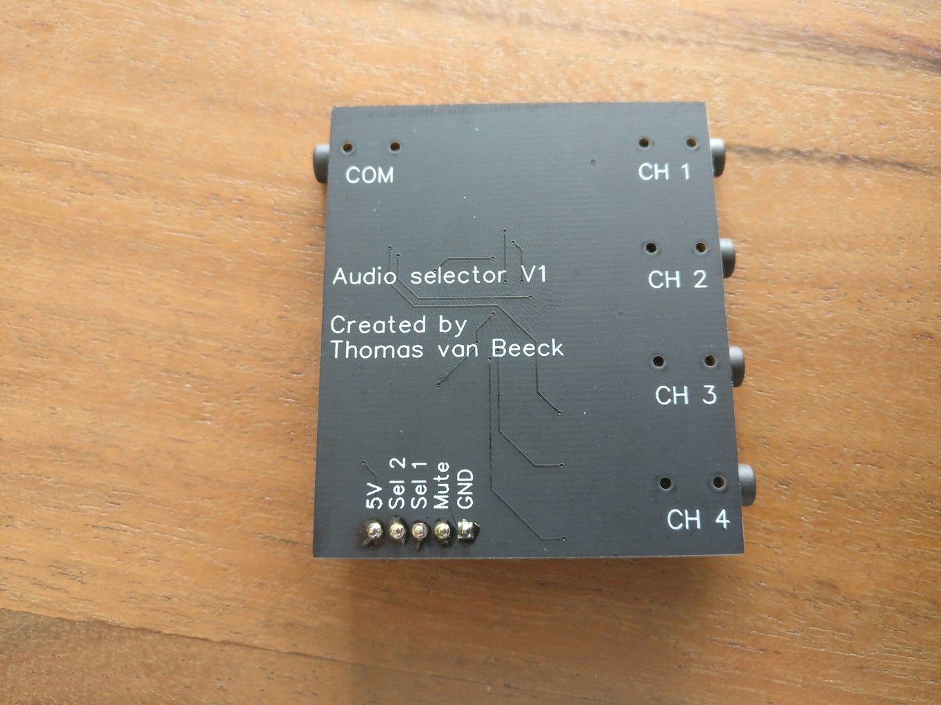

The first thing you will need to do is to power the board with 5 volt because it will not work without it. All logic also works on 5 volt. Connect Sel1, Sel2 and Mute to the arduino because they are not pulled up or down by any resistor. If they are not connected they will be floating wich will evoke weird hehavior.
This board has a mute functionality which will prevent any signal to travel trough the board. In its muted state all LEDs will light up. To mute the board pull the pin high.
To select a channel first mute should be disabled. With the two Sel pins you can select a channel according to the truth table.
Step 5: End
Thanks for checking out my instructable. I hope this was of any use to you. If you have any questions left leave them in the comments. Most of the time I reply within a few days.


