

Introduction: Auduino Build


Here is my Auduino build I made for a school project. I've been using the Auduino for a while without housing and decided it was time to make it a little container. It features four 5 Kilo Ohm potentiometers and one knob that swivels a door to exposes a photo resistor for an almost theremin effect. It's got an on and off switch and a 3.5 mm head phone jack. The only motorized machine I used for this was a metal band saw. If you don't have access to one you could easily do without one, by replacing tabs with brackets. I hope you guys build on what I've laid out and make your own designs and share them with me.
What you will need:
An Arduino rev 3 booted with Auduino ( reference this schematic for the final step )
9 volt battery clip with male barrel
A tiny breadboard
26 gauge galvanized steel 8x11 (consolidate for your unique build size)
A rivet gun
rivets, STD small head 1/8th inch
4 lock washers
4 potentiometeres, 5 Kilo ohm from radio shack (http://www.radioshack.com/5k-ohm-linear-taper-potentiometers/2711714.html#.VPIm4SygTTo)
One photo resistor
A spool of metal leads
Pliers
A power switch ( http://www.radioshack.com/spst-pc-mountable-submi... )
Digital calipers
T square
A 3.5mm head phone jack
(1) quarter inch rod (I used steel, http://www.mcmaster.com/#standard-steel-rod-stock... )
A 1/4th 20 thread count die (to thread the rod)
A box of hex nuts with a 20 thread count ( http://www.mcmaster.com/#hex-nuts/=w3wqd9 )
An engineering square
A vice (to grip the rod)
8 tiny screws and nuts, I used 1/8 ones
A utility knife
An awl
A hot glue gun
a hole punch with a 11/32", 1/8" bits and 3/32" bit
Finally access to a sheet metal bender
Optional:
Metal band saw
Step 1: Prototyping


Build a scale model of your case, my dimensions are 4.5" L x 4" W x 2" H. For my project I had to join 4 pieces of metal so I divided the top and the bottom and have two side pieces. I add 8, 1" x 1" tabs on the top piece bend into brackets, but I decided to only use the 4 tabs attached to the 4" sides of the top half. Disregard the other tabs.
Step 2: Bottom Plate and Sides


Before you cut your final pieces, test a scrap piece, make sure your sheet metal bender is making sharp corners and your sheet cutter is cutting square.
Lets make the bottom side first.
Use your scale model as a template.
Use the utility knife to measure and mark out a 4" x 4.5" square and cut.
Now lets make the sides.
Use the knife again for a 9" long 2" high rectangle. We over measure the length to compensate for the bend.
Use the metal square as a template and trace out 4"
Now use the sheet bender to bend exactly on the mark.
trace out 4.5" on the adjacent side and use the sheet cutter to cut that. (I used the bottom piece as a guide to make my mark)
You should now have a bent 8.5" L shaped piece of steel.
repeat this once more to complete the sides.
If you have something like the 4th image. Good job!.
Step 3: Top Piece and a Few Holes


Remember I scrapped the 8 tab idea and went with 4 tabs on the short 4" side.
So now we use the metal band saw and the sheet cutter to cut out our top piece. A 4" x 4.5" square with 2, 1" x 1" tabs on both of the 4" side. We eventually bend these and attach them to the side walls.
Okay so we are going to cut holes for 4 potentiometers, the on and off switch, a hole for the swivel knob and one more hole for the photo resistor.
I measure out the circumference of bottom parts of the potentiometer and space them out evenly, on top of top piece. I'm considering the space the machine screws will take up within, so the potentiometers dont get stabbed. I used a t-square to make my lines square.
Use the digital calipers to find the center of the potentiometers outline
Make a guide for the hole punch by using the awl to lightly mark the center of potentiometers outline. This helps the hole punch bit line itself up.
Use the hole punch with a 11/32 bit for each potentiometer. make sure you have lock washers to compensate for the little nubs on your potentiometers.
I then make a tiny hole above the first potentiometer hole, for my switch. I use a 3/32nd bit for this one, measured and marked with a utility knife and the awl. Make sure the switch isnt touching the base of any potentiometer!
Now two more holes for the photoresistor and the swivel door knob. Line up two 1/4 holes with the 2 middle potentiometer holes. I don't have an exact measurement for how far they should be from the edge, but around half an inch would be ideal.
Last hole. A quick hole punch for the 3.5mm head phone jack, you can use the 11/32 bit for this. I placed the hole behind and further to the right. It doesn't really matter where you place this, just don't obscure your photoresistor from the light.
There you go, 8 holes for the top. 4 potentiometer holes, one switch, one for the swivel rod, one for the photoresistor and one for the audio jack.
Step 4: Brackets and Pop Rivets


So the brackets aren't all that precise. They were cut and bent quickly on the sheet metal cutter and the sheet metal bender. Roughly a quarter inch wide and 2 inches long.
So in the first image, I'm feeding the brackets in the hole punch with a 1/8 bit. I use the bend and the rim of the punch as a guide to get a consistent distance for the hole. Maybe a quarter inch away from the bend.
First we are going to connect the side pieces to make a square.
So the third image is me using the awl to mark my corresponding holes, but a sharpie would work as well. I also use the engineering square to keep the brackets flush with the edge. Now that the holes have been punched, use the 8th inch rivets to lock them in place. If you haven't used a rivet gun before practice on a scrap piece.
The last image I situate the brackets like so, and attach only the bottom piece. Later we are going to hot glue hex nuts to the inside part of the brackets so we can attach screws and close our container.
Step 5: Steel Rod


Possibly the trickiest part to this is the steel rod.
First we want to thread the rod. Take note of the thread count of your die, to get the corresponding nut. I used a 20 thread per inch bit.
Lets first wrap tape around the rod before placing it in the vice to prevent scuffing the rod.
Tighten the vice and use a engineering square to get the rod level with the vice. The tricky part is using the die and threading squared with the rod. Its crucial for the threads to be as straight as possible or your swivel knob will be crooked. Hopefully you have a lot of rod to spare to get it right. Once the die is threading level, keep going a little past an inch, unless you have hex nuts longer than a quarter inch, then consolidate for 4 nuts.
Now lets bend a door. I used a scrap piece roughly a 1.5" long and .5" wide. I used the hole punch for a 1/4" hole on one end, then measured out how I want the piece to be bent. The door piece should be situated between the last two hex nuts, so bend the a portion the length of two hex nuts. Make sure the piece that touches the top sits tightly against the photo resistor hole. Test the resistance of the knob and tighten or loosen the hex nuts in accordance.
If you find the hex nuts loosening up when you use it, you could swap the last hex nut with a lock nut. Or put a dab of super glue on the threads to secure the nuts in place.
Step 6: Finally!

Here's the final few steps, attaching the Arduino and the machine screws.
Please excuse the disorganized innards of this thing.
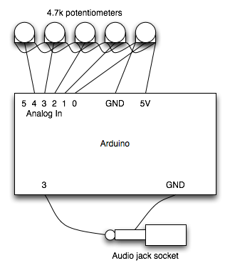
I used double stick tape on a piece of chipboard to attach it to the bottom plate of our box, one more to attach the Arduino to the chipboard. Then another piece for the breadboard on top of the Arduino.follow this schematic to attach your wires to the potentiometers and the audio jack:
http://farm4.static.flickr.com/3151/3038569386_fc8...
The photo resistor could be attach to any of the 5 parameters (2 grains, a frequency, decay for both and a pitch) like wise so could your potentiometers. Make sure your photo resistor is mounted below the hole where light enters. If its not receiving the way you want adjust the distance as you see fit.
I didn't solder my leads down, Used pliers to pin them down to the potentiometer leads
Stick the 9v battery down with double stick tape and connect the barrel to the female power jack of the Arduino. Cut the red wire and attach the loose wire to the switch leads, these should be soldered, but you could pin them in place with pliers.
Bend the top plates tabs and punch matching 1/8 holes on the tabs and side pieces. Screw in the switch, potentiometers (use the lock washers), audio jack the swivel door knob to the top plate and use the 1/8 screws with corresponding hex nuts to fix the top plate to the sides.
Now just hot glue the 1/8th nut to the insides of the bottom brackets and you're about done.
Optional: Use spray fixative to prevent rust for the edges that have been cut. For the untouched parts the galvanization process should prevent rust.
Thanks for reading. Please let me know if you have questions and share what you have made.

Participated in the
DIY Audio and Music Contest


