

Introduction: Automatic Control Hub for Mattress Heaters


We have electric 3 mattress heaters at home. Each is turned on/off by a momentary push button. It takes ~30 min to warm up and we always forget to turn them on in time. Timed electrical outlet doesn’t work, only pushing the button turns a heater on or off.
I came up with the following design to allow both automatic switching at desired times and manual override. In general this system can be used for remote control of various home devices turned on/off by toggle or momentary switches. User interface is implemented as a simplistic web server. It’s certainly a reinvention of the wheel, but I just used this as an excuse to tinker with RaspberryPi, Arduino and wireless communication modules :)
Step 1: Parts for Control Hub

Step 2: Parts for Each Receiver

Step 3: Connect NRF24L01 to RaspberryPi

Server running on RaspberryPi works as a hub controlling several Arduino-based edge devices, each one of them driving one or more switches.
I’ve chosen a more powerful NRF24L01+PA+LNA transceiver on the Raspberry side because of its greater range. Raspberry 3.3v PWR pin has no problem supplying enough current. Solder 10uF capacitor directly between Vcc and Gnd pins of the NRF24L01 to minimize supply glitches.
Then use 7 female-to-female jumper wires to connect transceiver with Raspberry according to the wiring diagram above
You need to enable SPI on your Raspberry and install NRF24 Python library.
Here is a excellent tutorial from Alexander Baran-Harper explaining how to do that
And this is a great document explaining RF24L01 module in general
Step 4: Assemble Receivers (aka Edge Devices)


I've chosen Arduino Nano - it’s both very cheap and has 3.3v output pin to supply NRF24L01. Btw, never connect NRF24L01 to 5V!
Hardware implementation for each device is the same. Their unique IDs will be set during programming. You can make as many edge devices as you need.
For mattress heater control only two Arduino digital pins were used
-Pin 2 drives the optocoupler, which essentially works as a miniature relay. When pin 2 is High, optocoupler short circuits its output pins thus acting like a momentary pushbutton switch .
-Pin 3 is connected to LED , useful for debugging of wireless connectivity.
Design is pretty generic, you can easily modify the system to use other digital pins for control of additional external switches. Pseudo-pcb layout may help you to position components more tightly on the breadboard and then connect them with wires. If someone is willing to develop a real PCB for this schematics it would be great.
Step 5: Programming the Devices

1.Download all the files
git clone https://github.com/bennywinefeld/HomeAutomation.g...
In the root directory there are files needed for programming the RaspberryPi
SwitchController.py - main Python program implementing the control hub
radioComm.py – low level procedures for sending/receiving data packages through NRF24L01
lib_nrf24.py - NRF24L01 free library, I post it for convenience
In arduinoEdgeDevice directory you will find:
arduinoEdgeDevice.ino - C code for Arduino
EdgeDeviceArduinoNano.fzz – Schematic of the edge device in Fritzing format
2. Program Arduinos
Each Arduino must have unique ID. Open arduinoEdgeDevice.ino and set for ex
#define BOARD_ID 0x02
After uploading this code to Arduino board it will have ID=2. When you power up the board it will blink 2 times – easy way to find out the ID.
To test that wireless communication between Raspberry and Arduino works run low level communication module directly from Raspberry unix shell, without starting the GUI hub: python radioComm.py 2
This will send 100 packets to Arduino with ID=2 and get 100 replies back. Each packet includes 5 bytes. For ex following packet is an instruction to Arduino with BOARD_ID==2 to set output pin 3 (the one connected to LED) to 1:
0x1 0x2 0xa4 0x3 0x1
The expected reply is 0x2 0x1 0xa4 0x3 0x1 - i.e the same packet with sender and receiver bytes transposed. As testing progresses you should see LED turning on and off and python code printing messages like
Transmission 95/100
  sending msg  0x1 0x2 0xa4 0x3 0x1, attempt 1/15
  got response 0x2 0x1 0xa4 0x3 0x1 in 0.04 sec
  message sent successfully
…
100/100 good transmissions, average num
of attempts = 1.04
Start your testing with transceivers near to each other. Maximal range depends from house to house.
3. Program Raspberry hub
If testing of communication went through fine, you can start the server.
First open SwitchController.py and modify the section which creates objects talking to edge devices, for ex
myHub.addEdgeDevice(EdgeDevice(2,"Yasha’s mattress heater", \
  [[2, PinTypes.momentary_switch, "21:30","22:00"], \
   [3,PinTypes.toggle_switch,"---","---"]] \
))
This creates an object communicating with Arduino edge device with ID=2. Digital pin 2, connected to the optocoupler is declared as a momentary switch. I.e to toggle the physical device (such as mattress heater) connected to it, we should send a sequence 0-1-0. 21:30 is automatic turn on time and 22:00 – turn off time.
Run python SwitchController.py to start the web server.
Here is one catch - we can’t take a reading of actual state of the heater. Whenever Raspberry server sends 0-1-0 sequence to pin 2 it assumes that the state of the heater flips. I.e if it was ON, it’s now OFF and vice versa. After sending a signal, server remembers the new state of the heater. But if you press the heater button manually, Raspberry knows nothing about this event and doesn’t update the state. Thus from this point it will do the opposite of the desired – i.e will turn the heater off at 21:30 and on at 22:30
While it’s quite possible to detect the real state of the heater and send it back to the server, this would require tinkering with the heater own circuit, which is very different from model to model.
Step 6: Expose Heater Momentary Switch Button Contacts
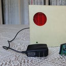
Now is time to connect the edge device to the heater. Open heater control box and locate the on/off button. In most models it will look like this one
Solder two 10-20cm long wires to diagonally opposed pins - any pair is fine. On the other end attach two female pin headers. They will connect to the male pin headers on Arduino. Polarity doesn’t matter.
Step 7: Accessing Control Hub Through Web Interface

My apologies for the ugly graphics, I’m very lousy as web developer :)
Navigate your web browser to <host>:8090. I installed Samba on my Raspberry, so router can resolve the host name. Otherwise you can simply type its IP address (show with sudo ifconfig command)
GUI will show you the status of all edge devices. Again – pin 2 is the one connected to the optocoupler. Pin 3 just turns on the LED
Clicking on Configure button brings the dialog box for the given edge device.
You can change start/end time or set the current state of both pins pins manually

Participated in the
Microcontroller Contest 2017


