

Introduction: BIG Disk Sander: Build, Use and Tips


I've lost count of the times when I have been mid project and thought, what I really want now is a nice big fat disk sander. With them you can make precise angles in wood and metal. You can produce brilliant outer edge curves, and very accurate circles. You can quickly remove material and flatten off stock that's too small to be safely planed, or thicknessed. You can sharpen tools, tidy up rough edges, deburr and square up, and do extreme toenail manicure (just in case you're insane, I'm not really recommending that last one).
In short, a disk sander is an awesomely useful machine to have in the shop!
Like most of my instructables, this one is mainly made from reclaimed materials.
Where is the bill of materials and tools used?? For this 'able it didn't make so much sense. a) because I'm using lots of strange materials that I have fished out of skips, and b) because I was experimenting with tools and techniques quite a lot. And c) if you're planning to build one you're going to read this all through and get an idea of what you need anyway based on what you already have available, right? I'll give tips on what might be useful reclaimed sources along the way.
If you're still not convinced you neeeed a disk sander, fly on ahead to the various steps on 'Use' to give you ideas and tips on what cool things you could do with one.
What makes a good disk sander?
OK so lets say you're thinking of buying one - what would you be looking for?
I'd say you'd want: a very strong solid base, good quiet, smooth and vibration free running, along with a perfectly flat and accurate work table with a parallel mitre slot. A tilting table seems like it would be a nice feature - but not at the expense of solidity. Something user friendly and safe - safety is obviously important.
Personally I'd want it BIG too. 500mm (20") abrasive disks are about the biggest economically available here in the UK, so that seems a good size to aim for. Having a nice big disk doesn't just mean you can sand bigger stuff, it also means you have a bigger range of abrasive speeds. That is, you can vary the material removal rate by choosing how far out from the centre of the disk you present the workpiece: towards the outer edge will be exceptionally aggressive, with the abrasive moving many times faster than say half way out.
When we look at fulfilling all those requirements in a bought machine, the cost is over £1.5k - which is quite a bit (eeeek!) - so lets make one from some rubbish!
Step 1: Mounting the Motor


I started with a 1kw single phase induction motor that I rescued from a broken floor scrubber/polisher we found in the skip. I was well pleased when I got it home, dried it out, and tested it. It went really well with very little vibration or noise, running at 1450rpm. At that speed, at the edge of a 20" disk, the abrasive will be travelling at roughly 38 meters per second - which is very fast!. But not too fast :D
This motor had a face mount, the design would have varied quite a bit if I was basing it round a foot mount motor.
I did some modification and used the housing/flange mount that came with the motor. To sit the motor horizontal I needed to support the rear end of the motor with something. For this, I glued two ply pieces together and routed a circle in them. Follow along with the notes on the photos for the whole story.
Step 2: Laminating a Work Table


A major part of the disk sander is a work table. Its basic function is to remain nice and solid at a set angle relative to the spinning disk. It is also usual, and extremely useful, to have a slot parallel to the disk. This is used for the mitre gauge (which is why it's often called a mitre slot) and other jigs and accessories.
I had some scrap aluminium sheet that we rescued from a skip (it was a backing to a really big black and white photo that presumably no one in the whole world liked). It was 2.5mm thick - not sturdy enough on its own, but...
Why not laminate some bits together, I thought. So I marked them up, and risked using the tablesaw with a non-ferrous metal cutting blade. I used a cast iron surface plate to try and achieve flatness while epoxy gluing three layers together.
I made the table big enough to overlap a 20" disk at either end.
Advantages of laminating:
The aluminium was free :)
I could fabricate a mitre slot along the length without a giant mill. To do this both the top layers are made up of two pieces, spaced out with some 1/2" parallels.
There will probably be some vibration damping of the table by virtue of the constrained layers of epoxy.
Disadvantages / what went wrong:
The epoxy was smelly, and squeezed out the edges of the joints. This wasn't a problem, apart from where it filled the mitre slot! Oh well I can deal with that later...
It's more complicated and takes time.
It is probably not as strong as a single beefy piece of aluminium because of the chance of de-lamination - so far it's held up well though. I put a few countersunk machine screws at strategic points, which puts the epoxy under compression. Meaning the only forces on it are likely to be shear forces - epoxy is very strong at resisting this kind of force.
Step 3: Table Relief Cut


This is just a case of angling the table's 'disk-meeting edge' so that when you adjust it to 45 degrees, the table will not catch on the disk.
My little mill is too small to make this cut all in one go, so there was some clamp re-jigging about involved. Worked out ok in the end.
Note- if you don't have a mill, I think this step could be completed at the end on the sander itself. Once you have the abrasive running on the disk, with care it should be possible to lower the table into the disk, and let it cut the relief (I imagine).
Step 4: Table's Frame & Vibration


So to make the table super rigid and sturdy, I added an under-frame. The frame also gives me some bits strong enough to house the pivot fixings. It's scrap aluminium extrusion I cut to size on the mitre saw - a hacksaw would have worked, if you can cut superhumanly square (or you already have a disk sander, with which you could quickly square up the rough cut - ahh the tool maker's paradox).
To attach the under-frame I used the same low viscosity, slow set epoxy: having roughened up all glue surfaces with an angle grinder. Note: The user Amclaussen, was kind enough to mention test he had with epoxy bonding aluminium. You can see the discussion in the comments, but the gist of it is that rough grit sanding is better than grinding, when it comes to improving bond strength. If I was doing it again I would probably go carefully with angle grinder with flap disk - hand sanding aluminium makes my soul ache.
To help prevent vibration and add still more rigidity, I filled in the spaces created by the frame with a home brew epoxy granite mix, with steel wire reinforcing.
Step 5: Motor Housing: Rigidity and Damping


I was coming on nicely with the table, so now I need to stiffen up the motor mount. I used a similar epoxy granite mixture, with steel wire reinforcing. I tamped the mixture down with a bit of scrap wood.
The mix is about 80% sand & small gravel : 20% out of date low viscosity epoxy.
I was quite pleased with the finish. It's a LOT stiffer, and vibration damping wise it just feels solid!
Step 6: Table Pivot Mounting


Attaching the table to the motor housing time.
I scored an awesome find during a dusty loft clear-out, with this thick metal bar - it was a bit rusty, but it's only very surface, and I found two long lengths :)
So anyway, sorry about the gloating, back to business. The bar is cut (with the steampunk power hacksaw) and drilled to accept some M12 8.8 bolts that act as a pivot. Then I drilled and tapped it for some perpendicular M6 clamping bolts. This locks the big bolts tightly (eek, wordy - just see the photo - you'll get the idea).
Step 7: Welding Up the Pivot Points


So after taking extra care to clamp, check squareness and dimensions, fiddle about, re-clamp, re-check squareness, and fiddle about some more, I tac-weld the pivot points in place.
For welding purposes, the steel bar is very thick so I ground bevels on the mating faces, which can be filed with weld fillet. This helps get a larger joining surface and stronger weld. I am using the welder on maximum power!
Once tacked in place we can mount the table, check it all fits (in my case it seems to!), before removing the table again and completing the weld.
You can expect it to warp a bit during the final welding, though you can minimise this by stitch-welding 1/2" sections. If it does warp, it's not too big a deal and can be adjusted out later...
Step 8: No Volt Release Switch

We are starting to get to the point where we are going to want to be testing this beast! It's never too early to add in a safe switch. I had this ready made no volt release switch (NVRS) hanging about from a box of random bits I picked up at an auction.
The NVRS basically prevents the tool from being powered up if power is cut and then restored. ie. It wont leap to life unexpectedly as you plug the socket in, or if the power comes on after a power cut.
If you dont have one you can make one from some easy to salvage components. Here's an instructable of a NVRS I made for a wood lathe.
WARNING: Mains electricity death! Please get help with wiring if you're in any way unsure (or prone to bouts of swaggering overconfidence).
Step 9: Casting the Hub & Trunnions Pt1


Like I said at the beginning, I was experimenting with lots of different techniques with this disk sander. I wanted to try casting the trunnions from scrap aluminium. Yep, before I go any further I should admit, I have no idea if they are technically called 'trunnions', but I don't know how else to describe them. Well whatever they are, you could make them from other materials, good quality plywood, for example, if the dimensions were suitably scaled-up.
Enough of the alternatives, here's my aluminium experiment:
I started by making the pattern from some shuttering ply, drawing out and cutting the shape on the bandsaw. I wanted two of them.
Next I chamfered the edges - this gives you a release angle - vertical edges would be impossible to remove from the casting sand.
I was in a bit of a rush, and the patterns could have been better, smoother, more identical, varnished etc. But I was hopeful they would do the job...
Step 10: Casting the Hub & Trunnions Pt2


Time to fire up the furnace!
I used a home made one in an old propane tank, using a blower from an old oil boiler.
Aluminium was melted (lots of info on the net on this if your interested in casting methods).
I poured into the mould for the trunnions, and the 'mould' for the hub: see pics...
There's soooo much information out there about aluminium casting that I'm not going to go into loads of detail here. An instructable search reveals some goodies, and I found the book "Metal Casting A Sand Casting Manual for the Small Foundry, Vol. 1" by Steve Chastain, 2004, really useful - it may well be at your local public library.
Step 11: Truing Up the Hub


So I would probably classify the frying pan mould experiment as a fail. The molten aluminium warped the pan so much that it created quite an odd shaped disk.
Still, I'm stubbornly pressing on with it and spent a LONG time on the metal lathe truing it up.
Step 12: Mounting the Hub


Ok this was a bit of a time consuming fiasco. Mainly because of the frying pan incident!
In the end though, I got the hub on there (tightly!) - and its made from scrap aluminium I had collected and melted.
Exasperated satisfaction....
Step 13: The Disk on the Hub


I pondered the idea of casting a big aluminium disk to cover the whole 20", but it seemed ambitious, and I wouldn't be able to true it up on the lathe. In the end I had a free evening in which I really wanted to make progress on the sander. I started thinking about making the pattern for the casting and found a square of plywood that was about the right size.
After cutting a circle out of it on the bandsaw, I started thinking that I could just as easily make the disk from the ply itself. Not quite as bling, but a lot easier and lighter.
Once I decided that, I used a top-bearing pattern bit with the router to cut a relief in the middle of the disk, so the hub and disk would fit...
Then I drilled 9 holes in both the disk and hub to fix it on. I made M5 threads in the aluminium hub, and counterbored the ply disk so the bolt heads were well below the surface.
Step 14: Truing Up the Ply Disk's Circumference


So the disk was only compass-line-freehand-bandsaw accurate and needed quite a bit of truing up.
The machine was borderline scary (in a bad way) when I first turned it on with the big unbalanced ply disk.
After truing it up with a lathe tool (that needed resharpening a lot!), it was much better.
Step 15: The Legs


We need more stability before re-fitting the table. As it was, any heavy weight placed on the table would unbalance the whole assembly.
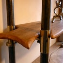
I had some bits of chainsaw milled ash left over from this lovely table I made which would make nice beefy legs (sorry for the blatant project plugs, cough, go like FE on facebook, cough, if you have read this far you will certainly enjoy it).
So yeah, I cut them so they were more alike on the bandsaw, flattened the bottoms on the jointer, and tidied up the surfaces with the thicknesser. Then I needed to cut some small relief grooves for the disk - I did that with good old handsaw and chisel.
To fix them on so they were exactly co-planer and flat I clamped them to the surface plate before screwing them up to the sides.
Step 16: Trunnion Clamps


So the trunnion clamps basically fix the angle of the table by clamping the trunnions in position.
I made them from threaded rod and two bits of scrap steel that sandwich the trunnion.
Step 17: Trunnion-table Interface Prep


I would call the aluminium trunnion castings rough and ready, but that would be an insult to the rough and ready genre. They should work though - with a little effort, that is.
Where they will bolt to the underside of the table needs to be nice and flat. I use the little mill to do this...
Step 18: Trunnion-table Interface


With the angle and face of the trunnions sorted, we now need to work out exactly how and where they join the table.
I installed a bit of flat steel bar, which I milled flat where it meets the trunnion.Then drilled and tapped appropriately, so the trunnion could bolt on.
Step 19: Trunnion Mounting Strips


I didn't really fill the space properly earlier, when I was epoxy-granite filling the table. So now was my chance to fill while embedding the flat bar in epoxy-granite.
Before I do that I bolt the steel strips on in just the right place, and mask their face.
Step 20: Mounting the Table


The moment of truth when it's time to bolt on the table!
It pleasingly fits together quite well, without any mega fettling.:D
Step 21: Tidying Up the Table Slot


I think I mentioned already, when I laminated the table together, some of the epoxy squoze out and pooled in the mitre slot. At the time I thought, no problem, I'll be able to scrape that out later with an old chisel or something.
How wrong I was!
So began the mission to rout out the epoxy, and a very small amout of the aluminium to achieve the perfectly straight slot.
I ended up using the saw guide, clamped down, and the router with a 1/2" Pattern bit.
This was exceptionally nerve wracking! I had the potential of trashing the whole table by loosing control of the router (it's only a hand router) and munching up the world. Well that's how it felt... See pic notes for details.
Step 22: Mitre Gauge 1 of 3 - Making a Semi Circle


It may seem strange to be going straight to making the mitre gauge, but I wanted that before I put abrasives on and did a first test because it will be instrumental in making the ply disk absolutely flat.
The mitre gauge is made from an old car disk brake cut in half. Follow along with the picture notes.
Step 23: Mitre Gauge 2 of 3 - Making a Square Angle


We need a piece of angle-iron to go on the front of the disk. I spent way too long cutting up and squaring a bit of old scrap. Again the pictures tell the story.
Step 24: Mitre Gauge 3 of 3 - Milling, Angle Arc & Assembly


So I basically fit the half-disk to the square angle, to form the base of a mitre gauge. I cut a strip of oak to sit in the table's slot.
Step 25: Truing Up the Disk


The plywood I used was a fairly old scrap. It was not flat and thus wibble-wobbled about horribly (technical term for bad run out).
Using a carbide insert lathe tool clamped to the mitre gauge I was able to slide it across the table, taking small cuts off the ply disk. This trued it up nicely.
This is why it was useful to make the mitre gauge before we even tested out the disk sander with an abrasive on yet.
After this I used a bit of sandpaper wrapped around a block to gently bring the surface, to super smooth, ready for the stick on abrasive disk .
Warning - to quote the Hackaday website "... Once these were cleaned up, a disk was mounted on the hub and trued up in the most unsafe manner possible." Which did make me chuckle - but there is some truth in that. This method works, but TO MAKE IT SAFER I recommend a MUCH beefier clamping system, and a way of being absolutely sure the back end of the tool cannot lift up, if the tool tip catches.
Step 26: Testing With Abrasive

I went ahead and stuck an abrasive disk on! I'm using the kind that have a peel off plastic backing. You can take them on and off by warming the glue with a heat gun. You can then put the plastic backing back on, so the abrasives can be re-used later.
It's turned on for the first time and makes some dust!
The dust extractor is bodged up temporarily so it sorta helps a bit..
Step 27: Balancing

Now that we have flattened off the disk, its a good time to balance the whole thing. There is a good instructable on this, and I pretty much followed the same procedure. So check it out here.
https://www.instructables.com/id/Dynamic-Motor-Balancing-with-Sugru-and-an-iPhone/
The only real difference to my method was that I didn't use sugru. Instead I cut a small channel in the back outside edge of the disk, which blue tack would nestle in nicely. Once I had calculated the position and weight needed, I used some small screws to add the weight more permanently.
Step 28: Dust Extractor Hood


So after the first test where I absolutely filled the workshop with airborne dust that settled on every exposed surface overnight, I concluded we need some good dust extraction. I wasn't hooking up the dust sniper to this one as I figured that a large volume of airflow might be better than high static pressure.
To start off I made a shroud that will cover the bottom part of the disk. It was made from a scrap of 10mm engineered oak floorboard (very common in skips and usually worth picking up). This shroud simply slots into some notches I cut into the legs.
I then cut a 150mm (6") hole in the board to make a dust collector port. Onto this we add a little ring (more floorboard) that just snaps round and retains the hose... The ring was drawn with a compass, cut on the bandsaw, and smoothed off on, you guessed it, the new disk sander!
Step 29: Guarding


Whenever you have fast and powerful spinning things, it is important to think safety. The first couple of times you are using it, it may not seem necessary, but years down the line, when you have forgotten the danger is there, or when your friend comes to visit...
So yeah, I strongly suggest guarding all the spinning bits that you don't need constant access to in order for the machine to work.
Scrap bicycle rims (from a 24" wheel) and some more floor board seemed to fit the bill nicely. See pic's notes for details.
Step 30: Metal Dust Collector


AKA magnets!
I used a little round scrap of plastic, I forget what it was from (it was in the round disks box along with all my hole-saw scraps), and glued some metal magnet backings from an old microwave to it. I fixed just the metal backings, so the magnets themselves can be removed and 'emptied'.
The magnets are wrapped in thin plastic bags, so 'emptying' is as simple as pulling the bag off with the metal dust inside.
As an aside - keep the iron filings for other projects - it's a cool additive to various concoctions...
Update & Warning: so turns out the plastic bags round the magnets to conveniently capture the dust wasn't such a good idea - they quickly caught on fire from the hot sparks. This is fun and exciting but smelly and potentially very dangerous. So yeah, bags not recommended, just clean the magnets off without them. It's not as easy but it's safe.
Step 31: Use 1: General Usage and Safety, Tilting Table & Sanding to a Line.
It's time to get this machine working! There are a bunch of 'Use' steps. Most of them have videos on different aspects of using a disk sander.First check out the intro video on this step - it goes over general use and some safety points.
The second video in this step is a discussion (with myself) about the benefits (or not) of having a tilting table.
A few points not mentioned in the videos:
As with most machines with spinning bits, eye protection is a must. A dust mask is also wise. A fast acting brake and kick emergency stop switch would be a useful addition to this project.
Step 32: Use 2: Precise Angles

See the video. You can make precise angles in small things that would be dangerous on a tablesaw or mitre saw, and you can quickly square up metal stock.
Step 33: Use 3: Exact Circle Sanding Jig


I made this from some more of the old engineered floorboard, and a few scraps of oak. Check out the photo's notes for build information.
As well as circles the jig is also very good at making arches - anything roundish really. See the video for an explanation of the circle making jig's use.
Step 34: Use 4: Small Parts - Zero Clearance

So this is one of the best things about a disk sander - the ability to straighten up, square off and smooth small parts that won't fit on a table saw or planer.
To do it safely you really want to have the edge nearest the disk fully supported so the part doesn't up end and get stuck. To do this I have been using the circle cutting jig base which goes right up to the abrasive.
I'm torn as to whether, if building the machine again, I would make the table come right up to the disk. The advantage would be better support for the workpiece, but the disadvantage would be that the table would have to be taken right off to switch over abrasives - as it is I can get them on and off without doing that (though it's still a bit fiddly).
Step 35: Use 5: Tool Sharpening Jig


The disk sander is really good at sharpening. Using a reasonably course grit, like 80, you can quickly take out big nicks, and renovate old chisels and planer blades. I have a wetstone grinder, but it isn't aggressive enough to remove nicks in a reasonable time frame - this works much better for that. You can go razor sharp all with the disk sander if you can be bothered to change grits on the disk. I haven't had the disk sander long enough to know what my process will be, but thus far I've hogged off material on the disk removing nicks and making them perfectly square, and then given a razor micro bevel on the wetstone - that worked well.
I made a jig to help get the angles spot on. It works with the circle cutting jig base (see photos). I don't have video of this one, but there is a random axe sharpening one...
Important note: It is quite possible to overheat the cutting edge of chisels (especially at the outer edge of a 20" abrasive disk!), so don't overdo it. I tend to have a container of water nearby that I periodically dunk the chisel into to cool it off (that can be done without un-clamping it from the sharpening jig. It's also a good idea to move the chisel back and forth, to evenly wear the abrasive disk...
If you do 'blue' the edge, you can simply remove that section of metal, by further (and more careful) grinding, but it takes a while. Not that I've ever needed to do that when I started woodworking, of course. Certainly not.
Step 36: Signing Off

I hope some of this was helpful to you. The project was quite a fun one for me, as I was experimenting with unusual materials (aluminium casting and epoxy granite), and as always, it was a learning experience. It hasn't been finished long, but I reckon this is going to be a very useful addition to the shop. But...
I did just want to mention that I have been doing woodworking some time, and have gotten by ok without a disk sander until now... So yeah, the more tools at your disposal the better - they do open up new possibilities. I guess the moral of the story is, you don't need fancy tools to be creative, but they help ;)
most of the time...
Anyway, if you liked this or found it useful please go like the Flowering Elbow page on facebook, where I post my latest experiments and check out some more recent projects on my YouTube channel.

Grand Prize in the
Tools Contest


