

Introduction: BackCam or How I Learned to Stop Worrying and Love Not Having to Turn My Head

Finding the need to be able to see directly behind me as well as in front with out have to use time to turn around rather frequently (something the old Bat-suit could have used before the neck upgrade), I wanted to create something that would let me see behind me as well as far away with little effort if I am in a tight situation. Two cameras are connected to one monitor on my wrist. The first camera is on my back and the second one will be mounted on a paintball gun so that I can take cover and continue shooting. The second camera could also be a wireless camera that is up in a tree somewhere to get an aerial view.
Trying to use only material I had around the house, I set off on a creating adventure!!
Step 1: Parts


Hip gear screen pad (or other small lcd monitor)
One or two small wired surveillance cameras
(optional wireless surveillance camera)
2x Female rca jack (taken from an old camcorder or vcr…)
2x RCA Cable I am using the white and yellow
2x Trimmer pot (thin) from old radio
Perforated PC board
Extra wire
Momentary switch
2x SPDT switch (one from hip gear screen other from old camcorder or radioshack…)
3x 9volt batteries + connectors
Material to act like a watch band (I used an old elastic strap from an ankle brace)
Dremel
Soldering iron+ solder
Hot glue
Scarf, jacket, shirt to hide the first camera
Paintball gun or the like for the second gun, or wherever you want to put it
Step 2: Dismantling

On the back of the Hip Gear monitor there are 6 screws that need to be removed.
Start with the two bottom ones that are at the hinge, one will be under the white "Q. C. Passed" sticker.
From there go ahead and remover the remaining 4 screws and take off the monitor's back cover.
There are now 2 screws on the board for the monitor and under that 3 for the control board for the screen brightness, contrast and color as well as volume.
Remove everything from the inside of the case and put it aside, now separate the monitor case from the rest of the controller. We will only be using the monitor case for this project.
After everything is taken out you can now clearly see the two boards, the screen and the two speakers. I don't need sound so we can clip the speakers off and remove them from the case two. I trimmed down the area the held the speakers in so that it was level.
Step 3: Wiring the Boards


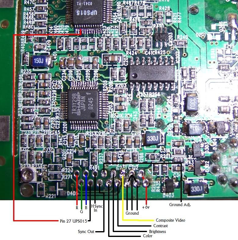
From the main square monitor board there are seven cables bound together one of them is colored pink and it is the positive voltage. There are also two other wires on the other side of this group, Brown and yellow. These are important, the brown one goes to the ground on the video and the yellow is the positive on the video.
Using a schematic (http://i18.photobucket.com/albums/b134/Segasonicfan/hipgearpinout.jpg) I found on the benheck.com forums from segasonicfan I was able to figure out each wire and from that feel free to cut off the image control board and wire mine own so that every thing could be quite smaller.
Using two thin trimmer pots from an old radio (volume and frequency control) and the 4 resistors from the original image control board I was able to make a much smaller one that controlled just brightness and contrast. The default color was fine but the brightness was too bright and the contrast was odd. following the pinout from the board I replicated it on the new PC board.
Step 4: Video Input Switch


We will now make the circuit to be able to switch between the two cameras on the one monitor.
Normally you would use a DPDT switch but the one I had was too big for the project so I made the equivalent of one out of two SPDT switches.
You connect the outer shell pin (ground) of the first RCA female jack to the top right pin on the switch and the inner pin (+) to the upper left pin on the switch and then for the second RCA jack the outer pin to the lowest right pin and then the inner pin on the jack to the lowest left pin on the switch. the right and left middle pins on the switch are used to transmit the signal to the screen. The right one is for the ground and the left one is for the positive voltage on the board. This switch makes it so that the screen will show camera 1 when the switch is up and camera two when the switch is down. Because I used two SPDT switches I need to flip two switches instead of one is all.
Step 5: Placement and Battery


Now that the video-in switch is taken care of you can start placing the monitor and other parts into the case. I cut the case down a bit to access the RCA plugs and the switch. I also used a dremel to cut off the bottom part of the case under the monitor where the screen control nobs were to save more space and to make it look a little better.
Hot glue the screen in first and then the video switch so that the monitor board will fit properly. A 9volt battery should fit snugly in over the old speaker spot.
I wanted two switches for the monitor to turn on, one momentary switch in the palm of my hand and another on/off switch that would stay on in case I needed my left hand but needed the screen to stay on. I used another SPDT switch and wired it in after the battery but before the momentary switch to bypass it if needed.
For the bottom half of the case I needed to cut some slits to insert a wrist band so that I could actually wears this. Again using a Dremel I cut two slits on either side and inserted the wristband from an old ankle brace.
Step 6: Wearability and Fun


I plan to mount one camera on the back of a molle tactical vest and the other on a paintball gun like I said earlier. You can hide the first camera in a scarf or under the hood of a hoodie, up to you and your fashion sense. A switch could also be added to each of the batteries powering the cameras to save power when not in use. If you choose to make something like this I would like to see it.

Participated in the
Spy Challenge


