

Introduction: Bit the "Follow-Me" RoboDawg


So I have been thinking about creating a robot companion of some kind for a few years now and have finally gotten around to doing it. I also recruited a few friends to get in on the action as well. It is working surprisingly well for a first go at things. I have taken my robot dog to my work place on a number of occasions and have gotten a number of compliments (as well as strange looks. Lol). The project is by no means perfect (or complete), but we figured this would be a good place to share our progress and give everyone a chance to build their own. You can follow the project's Hackaday.io page and GitHub repository as we continue to develop. Please comment with suggestions, critiques, etc. They are much appreciated.
Here we go. Bit the RoboDawg Version 1.0.
Step 1: Explanation of Bit


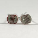
Bit is controlled using light. The pet owner carries a light source (BitBeacon) that shines an IR light at a specified frequency (BitFrequency = 7.8 kHz). Bit has a light sensor circuit (BitReceptor) that contains 4 photodiodes positioned at north, south, east, and west. When the light hits BitReceptor the relative intensity at each of the photodiodes determines the direction that Bit should travel. For example, if the intensity at the north sensor is the highest, then Bit travels due north. If the intensity at the north and east sensors are higher than west and south and are relatively comparable to each other, then Bit travels due northeast.
Bit contains a simple motor driver circuit using two h-bridges to control motor speed. We included a few other features to make Bit act a little more dog-like. We included an audio playback circuit that barks whenever Bit gets close to its owner. When Bit gets really close to the BitBeacon, all light sensors on the BitReceptor are at maximum intensity. When this occurs, we have a simple logic circuit that activates the audio playback circuit and Bit responds with a bark! Additionally, with a piezo sensor, Bit can also respond will also bark when petted. So a few cool features to make Bit more dog-like. We also want to add voice commands and things like that as well, but we think this is a pretty good start!
Step 2: Gather Your Tools

This project is relatively involved.
There is quite a bit of general circuit designing, printed circuit board designing, and soldering.
We have been updating a Bill of Materials (BOM), so please refer to it in order to get a list of parts that you need. Additionally, you will need a soldering station to put together the BitBeacon. Or you could recreate a circuit on a breadboard if you would like, but I recommend going the circuit board option or things will start to get pretty messy.
Step 3: Assemble the Chassis

We used a robot chassis from SparkFun as a first go around. It has its quirks, but it works for us. SparkFun has instructions on how to assemble the chassis. The kit also comes with the same instructions that's on SparkFun's website.
Step 4: Motor Driver Circuit


We used the SN754410 quadruple half H-bridge. These guys are pin for pin replacements for the popular L293D H-bridges, but allow for higher current (1 A as opposed to 0.6 A). The connections for these are pretty easy.
The chassis has 4 motors for each 4 wheels. We use 2 motor drivers to control 4 motors (a single SN754410 can control 2 motors). One H bridge controls the back left motor and the back right motor. The other H bridge controls the front left motor and the front right motor. The only tricky part is we are controlling the motor drivers in parallel so that the left motors move together and the right motors move together.
Motor speed is controlled using pulse-width modulation of the Arduino's digital pins. PWM is explained more here.
Step 5: Order the PCB

We have shared the PCB order for the BitReceptor on OSH Park. You can use the link to order the board directly.
Step 6: Assemble the BitReceptor Circuit


This may be a bit difficult if you are relatively new to electronics. The design uses surface mount components (SMD). This allows us to make the design a lot smaller and cheaper since price is more or less the only cost driver on OSH Park. Smaller boards make for sleeker products in my opinion.
The design is pretty simple. All four sensors (north, south, east, and west) use the same circuit. The first stage is a transimpedance amplifier that converts the current from the photodiode (A photodiode is a component that converts light to current. For a more in-depth explanation of photodiodes, navigate here.) to a voltage. Afterwards, there are three consecutive bandpass filter circuits with really high gain. We wanted to be able to control Bit from 15 feet away so we need to amplify the photocurrent a lot in order to get a usable signal. The final stage (diode and capacitor) is a peak detector circuit. The peak detector circuit essentially allows us to convert the AC BitBeacon signal to a DC voltage for easy processing by a microcontroller.
There are a few modifications to the circuit board that were made after the fact. We added a 2.2k resistor in parallel with the capacitor for the peak detector. We also added a 1uF capacitor in parallel as well. The 2.2k resistor and 1uF capacitor were added off-board when the BitReceptor was placed on a breadboard. We realized we needed a different "time constant" to respond quickly enough to the BitFrequency (7.8kHz), but discharge fast enough to respond to changes in the light intensity.
North output is sent to A0, West to A1, and East to A2. South was not utilized in the current iteration.
Step 7: Assemble the BitBeacon


We ordered a circuit board for the BitBeacon, but had trouble getting it to work. We eventually changed the design pretty dramatically anyway, so we did not worry about the board we previously ordered. The BitBeacon is relatively straightforward, but has a number of parts. The sections are detailed below.
1. Square wave oscillator
2. Square to sine wave filter
3. Sine wave gain stage
4. LED driver stage
5. AC circuit checker
6. Power indicator LED
7. Voltage Regulator
Square Wave Oscillator
We use a square wave oscillator which produces a square wave at our BitFrequency (7.8kHz). The square wave is filtered to a sine wave so we can have sine wave excitation of our LEDs. The LED driver stage is a simple bipolar junction transistor (BJT) circuit to drive the high current, super bright LEDs. Using a BJT also allows us to easily set the current through the LEDs and control the brightness. You can learn more about BJTs here.
AC checker
The AC checker circuit gives us a visual sanity check to ensure we have proper oscillation at the desired frequency. The sine wave used to drive the LEDs is also sent through a high pass filter (cutoff frequency at the BitFrequency 7.8kHz). This ensures that the LED will only light up with an AC signal that has a peak amplitude above the forward voltage of the LED.
Power Indicator
The power indicator lets us know our battery still has juice in it.
Voltage Regulator
The voltage regulator allows us to use a 9V battery to power our circuit. The 9V from the battery is regulated to 5V.
You can learn more about BJTs here, LEDs here, oscillators here, AC signals here, and filters here.
Step 8: Bark! Circuit


For the Bark circuit, I used a Digital Recording Module that I purchased from RadioShack a few years ago. The module allows you to record a sound (up to 20 seconds) and plays back the sound at a push of a button. The memory is non-volatile (which means the sound does not get erased when the module loses power). I simply found a cool sounding dog bark and recorded the sound. I did a bit of modifications to breakout some of the connections of the recording module. I removed the playback button and soldered a wire to the connections instead. This way I could control the playback using my own circuit. For the recording module, the button shorts a pull-up resistor to ground. I simply found the resistor the button was connected to and attached the resistor to an n-type MOSFET so I could control the playback using an Arduino. As you probably noticed, the recording module has a 9V battery snap connector. The 9V battery source feeds into a 5V regulator which powers the module. I bypassed the regulator by soldering a wire to its output and attaching it to 5V regulator output that's already on Bit. This way I did not need an additional battery for the module since Bit can provide a power source.
Step 9: Petting Detection

For the petting detection, we used a simple piezo electric sensor circuit. A piezo element produces a voltage when pressure is applied to it. This voltage is then regulated with a zener diode which prevents the voltage from exceeding a certain value (3.3 V in our case). This voltage is then sent to the analog input pin on the Arduino through a rectifier diode. The rectifier diode prevents negative voltages from going to the Arduino. This is a pretty crude sensing circuit and will need to be improved, but it is functional.
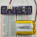
Step 10: Optional Bluetooth Module

The code contains debugging information that is sent over serial and with Bluetooth. Feel free to add a Bluetooth module to the project. You can view the information on your Android phone using a Bluetooth terminal like BlueTerm. In the code, the TX and RX pins of the Bluetooth module are attached to digital pins 2 and 3 respectively.
Step 11: Upload the Code

The algorithm to determine direction is pretty simple. If the BitBeacon (light emitter circuit) is hitting the north sensor directly, then the intensity at north will be the highest, while the intensity at west and east should be relatively similar due to the beam spread (please refer to image). As a result, Bit will move due north and both the left and right motors will move at the same speed so Bit goes straight forward.
If the BitBeacon is in between the north and the east sensors (or the north and the west sensors), then the intensity at the north and east sensors should be about the same. As a result, Bit should move due north-east. This is accomplished by moving the left motors forward at a higher speed than the right motors.
If the BitBeacon is pointing directly towards the east sensor (or the west sensor), then the intensity at the east sensor should be much higher than the north sensor and the intensity at the west sensor should be zero. As a result, Bit will move due east. This is accomplished by moving the left motors forward and the right motors backwards so that Bit will turn on a dime.
We are actively updating the code so many changes will come. Attached is the current stable version for this iteration, but feel free to follow the GitHub repository to see what other modifications we make later down the road.
Attachments

Step 12: Comments and Future Directions


This is a work in progress. There are a number of bugs we are addressing and a number of added functionality that we want to add like a proximity sensor for wall avoidance and a voice recognition module for voice commands. The BitBeacon is not currently situated to be placed on someone's back or belt buckle and have Bit follow. We still have to "direct" Bit in some ways, especially when going through doors. The BitReceptor gets saturated when in direct sunlight. We think we have a fix for that, but it hasn't been tested fully. The BitReceptor is also really noisy due to its really high gain. And a number of other things, but we figured this is a good spot to share our progress.
If you want to follow along, visit the project's Hackaday.io page. We post updates on what we are working on fairly regularly. Also follow the project's GitHub repository. We make changes very frequently.

Participated in the
Dog Challenge 2016

Participated in the
DIY Summer Camp Challenge

Participated in the
Makerspace Contest


