

Introduction: Blinking LED Using ARM7 LPC2148 Microcontroller


This is a beginner tutorial to make an understanding of 32-bit microcontrollers. ARM is a 32-bit reduced instruction set computer (RISC) developed by ARM(previously Acorn Risk Machine) Holdings. The ARM architecture is the most widely used 32-bit in terms of numbers produced. The simplicity of ARM processors are of low power applications. Hence, better in the mobile and embedded electronics market, as relatively low-cost, small microprocessors and microcontrollers.
ARM 7
Introduced in 1994, the ARM7™ processor family has been immensely successful, and has helped establish ARM as the architecture of choice in the digital world. Over the years, more than 10 billion ARM7 processor family-based devices have powered a wide variety of cost and power-sensitive applications. While the ARM7 processor family continues to be used today for simple 32-bit devices, newer embedded designs are increasingly making use of latest ARM processors such as the Cortex M0 and Cortex M3 processors, both of which offer significant technical enhancements over the ARM7 family.
LPC 2148
LPC2148 is the widely used IC from ARM-7 family. It is manufactured by Philips and it is pre-loaded with many inbuilt peripherals making it more efficient and a reliable option for the beginners as well as high end application developer.
LED
LED does not emit white light, but LEDs emit nearly monochromatic light, making them highly efficient for colored light applications such as traffic lights and exit signs. However, to be used as a general light source, white light is needed.
White light can be achieved with LEDs in three ways:
- Phosphor conversion, in which a phosphor is used on or near the LED to convert the colored light to white light.
- RGB systems, in which light from multiple monochromatic LEDs (e.g., red, green, and blue) is mixed, resulting in white light.
- A hybrid method, which uses both phosphor-converted (PC) and monochromatic LEDs.The potential of LED technology to produce high-quality white light with unprecedented energy efficiency is the primary motivation for the intense level of research and developmentcurrently supported by the U.S. Department of Energy.
Step 1: ARM7 Architecture


Data Sizes and Instruction Sets
- When used in relation to the ARM:
---Halfword means 16 bits (two bytes)
---Word means 32 bits (four bytes)
---Doubleword means 64 bits (eight bytes)
- Most ARMs implement two instruction sets
---32-bit ARM Instruction Set
---16-bit Thumb Instruction Set
- Latest ARM cores introduce a new instruction set Thumb-2
---Provides a mixture of 32-bit and 16-bit instructions
---Maintains code density with increased flexibility
- Jazelle-DBX cores can also execute Java bytecode
Processor Modes
Given above figure....
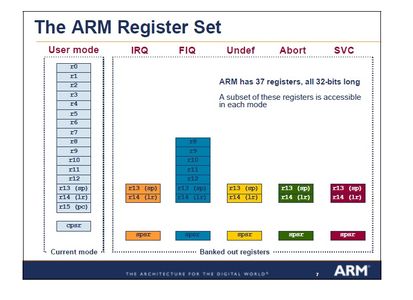
Register Sets
Given above figure....
Status Registers
Given above figure....
Step 2: LPC2148 Details
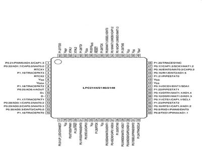


LPC2148 is the widely used IC from ARM-7 family. It is manufactured by Philips and it is pre-loaded with many inbuilt peripherals making it more efficient and a reliable option for the beginners as well as high end application developer.
Features of LPC214x series controllers:
– 16-bit/32-bit ARM7TDMI-S microcontroller
– 40 kB of on-chip static RAM and 512 kB of on-chip flash memory. 128-bit wide interface/accelerator enables high-speed 60 MHz operation.
– In-System Programming/In-Application Programming (ISP/IAP) via on-chip boot loader software. Single flash sector or full chip erase in 400 ms and programming of 256 B in 1 ms.
– EmbeddedICE RT and Embedded Trace interfaces offer real-time debugging with the on-chip RealMonitor software and high-speed tracing of instruction execution.
– USB 2.0 Full-speed compliant device controller with 2 kB of endpoint RAM. In addition, the LPC2146/48 provides 8 kB of on-chip RAM accessible to USB by DMA.
– Two 10-bit ADCs provide a total of 14 analog inputs, with conversion times as low as 2.44 ms per channel.
– Single 10-bit DAC provides variable analog output
– Two 32-bit timers/external event counters (with four capture and four compare channels each), PWM unit (six outputs) and watchdog.
– Low power Real-Time Clock (RTC) with independent power and 32 kHz clock input.
– Multiple serial interfaces including two UARTs (16C550), two Fast I2C-bus (400 kbit/s), SPI and SSP with buffering and variable data length capabilities.
– Vectored Interrupt Controller (VIC) with configurable priorities and vector addresses.
– Up to 45 of 5 V tolerant fast general purpose I/O pins in a tiny LQFP64 package.
– Up to 21 external interrupt pins available.
– 60 MHz maximum CPU clock available from programmable on-chip PLL with settling time of 100 ms.
– On-chip integrated oscillator operates with an external crystal from 1 MHz to 25 MHz.
– Power saving modes include Idle and Power-down.
– Individual enable/disable of peripheral functions as well as peripheral clock scaling for additional power optimization.
– Processor wake-up from Power-down mode via external interrupt or BOD.
– Single power supply chip with POR and BOD circuits:
. . . . . . – CPU operating voltage range of 3.0 V to 3.6 V (3.3 V ± 10 %) with 5 V tolerant I/O pads.
EasyARM7 Board-Features
- On-board NXP’s LPC2148 microcontroller with serial bootloader
- USB powered or externally powered
- On board USB to Serial converter to implement UART communication using the standard USB port on the computer
- The USB to Serial Converter can also be used as a programmer to program the device
- Breakout to all the port pins for interfacing external circuits and ADD-ONsOn-board crystal of 12MHz to clock the microcontroller
- On-board crystal of 32.768kHz to clock the on-chip RTCProtection diodes for external power to the microcontroller and RTC battery backupPush button to hardware reset the MCUOne on-board LED to display status of a GPIO pinBreadboard compatible development boardWell-documented top and bottom side for easy hardware troubleshooting.
POWER SUPPLY
LPC-P2148 can take power from three sources:
– External power supply 5.0V DC
– +5V_USB from USB connector
– Extension pins VIN and GND
RESET
LPC2148 pin 57 (RST) and RESET button.
CLOCK
- Quartz crystal with name Q1 (12 MHz) is connected to LPC2148 pin 61 (X2) and pin 62 (X1).
- Quartz crystal with name Q2 (32.768 kHz) is connected to LPC2148 pin 3 (RTCX1) and pin 5 (RTCX2).
Step 3: LPC2148 With LED Connection Diagram
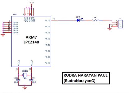
Above is the circuit diagram for ARM7-LPC2148 chip with LED.
If you have ready made boards, then just connect P1.16(pin) with 1k resistance-----> +5v.
When P1.16 status is High(+5v), then LED will not glow and when P1.16 is at Low(0v) status then LED will glow.
[P1.16/TRACEPKT0] — General purpose input/output digital pin (GPIO). Standard I/O port with internal pull-up.
---- TRACEPKT0 — Trace Packet, bit 0.
IOPIN: The current state of the GPIO configured port pins can always be read from this register, regardless of pin direction.THEY are----
- IO0PIN(PORT0) &
- IO1PIN(PORT1)
IODIR: GPIO Port Direction control register. This register individually controls the direction of each port pin.
- IO0DIR(PORT0) &
- IO1DIR(PORT1)
Step 4: Coding
/*HERE IS THE CODE FOR LED-BLINKING*/
#include <LPC214X.H>
// Define LPC2148 Header File
#define led IO1PIN // Define LED to Port1
#define tled IO1DIR // Define Port1 as output
void delay(int x);
int main()
{
PINSEL2 = 0x00000000; // Define port lines as GPIO
tled = 0x00010000; // Define P1.16as O/P
led = 0x00000000; // Define P1.16 as zero
while(1) // Loop forever
{
led = 0x00010000; // Turn ON P1.16
delay(2000);
led = 0x00000000; // Turn OFF P1.16
delay(1500);
}
return 0;
}
void delay(int x)
{
unsigned int k,l;
for(k = x;k > 0;k--)
for(l = 0;l < x;l++);
}
Step 5: Implementation to Microconrollers
Software Needed:
- The KEIL IDE(uvision4): They must be properly set up and a project with correct settings must be created in order to compile the code.
- Hex file will generate for LPC2148 chip.
- Flash Magic tool is used to download the hex file into LPC2148 through USB-UART port.
- Driver for USB-UART(RS232) CP2102 chip IS GIVEN ABOBE......
General Information
- For proper working use the components of exact values as shown in Circuit file.
- Wherever possible use new components. Solder everything in a clean way.
- A major problem arises due to improper soldering, solder jumps and loose joints.
- Use the exact value crystal shown in schematic.


