

Introduction: Boat Autopilot - Based on the Arduino


Here's how to build an autopilot which can steer an RC boat to waypoints! It's easy to build, based on the popular Arduino platform, and great for hobbyists who want some soldering practice! With this autopilot, an RC boat can go long distances without any human intervention, like an autonomous drone. The original idea was to mimic robotic boats like the UBC Sailbot, and the Scout (which almost successfully completed its trans-atlantic voyage!)
This project has been in the making for over a year now, and has taught me a lot about autopilot theory and circuit design. Hopefully, one day, I'll be able to take the skills used to make this autopilot, and apply them to make an autopilot for my dad's 38 foot catamaran!
To get to the final version of this autopilot, I went through three main prototypes. Each prototype got increasingly more complex in terms of circuitry and code. After those three prototypes, I built the final circuit, which was able to steer an RC boat around a pond multiple times. Very detailed schematics and pictures are available if you want to build your own.
The final version is bug-free, but still has room for improvement. In terms of code, I still need to get the boat to follow a path, and not simply go to a waypoint (this counteracts sideways drift). In terms of electronics, I'm hoping to add an accelerometer in order to add tilt-compensation to my compass.
Step 1: Video Overview and Autopilot Explaination
Here's a short video that goes over the project, the prototypes, some theory, and more!
Step 2: Prototype #1


The first prototype of the autopilot was very basic. The goal was to build a device that could:
- Read the location from a GPS
- Read the bearing from a compass
- Steer a rudder servo
- Test formulas which are necessary for making a real autopilot
- Use the rudder to keep a bearing
For this early prototype I decided on using an Arduino Uno for the brains; I would switch over to a barebones Arduino design (AtMega328) in the final version.
Reading a GPS
For the first prototype, I wanted the cheapest possible GPS I could get my hands on, so I went with the $8 UBlox PCI-5s. To connect the GPS to the Arduino, all I had to do was solder four wires to the back of the card, connect them to Arduino, then attach an antenna. I used the TinyGPS++ library to parse incoming serial data, which allowed me to get the current location, speed, direction, and more! Here's my other Instructable on how to implement this chip. I used this GPS up until the third prototype, where I replaced it with another one.
Reading a Compass
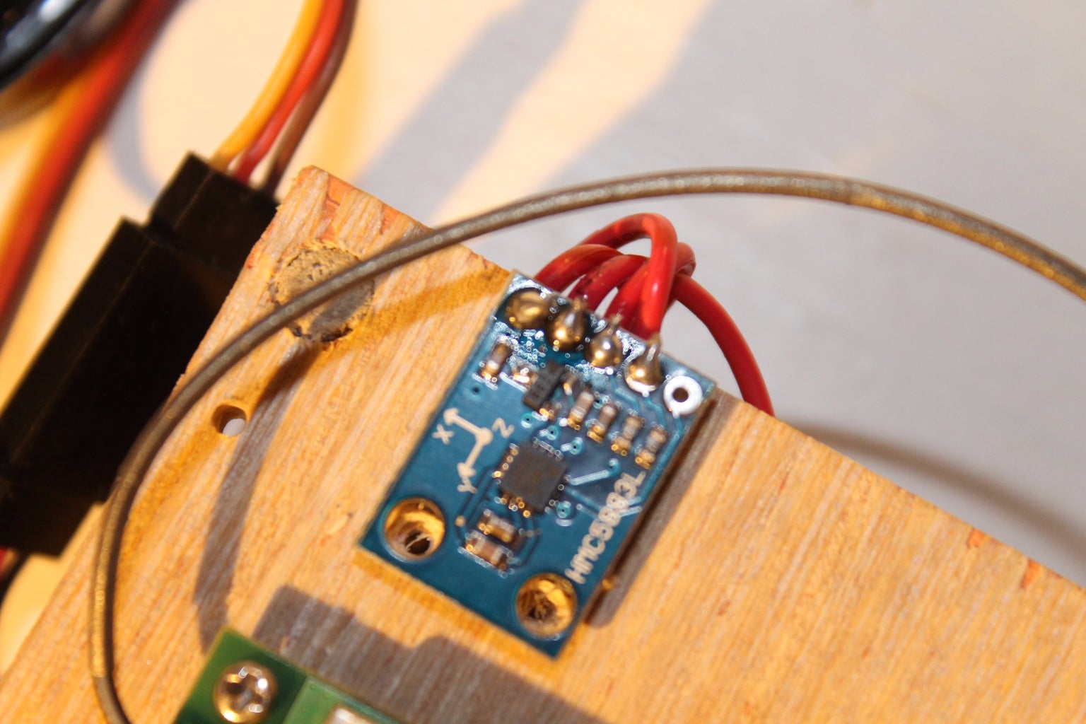
The compass I used is the HMC5883L, which connects to the Arduino through I2C. Bildr has a very nice tutorial on how to connect this compass to the Arduino. To read the bearing I used this Arduino library.
Steering a Servo
Steering a servo with an Arduino is incredibly easy, but not when the SoftwareSerial library (necessary for TinyGPS++) interferes with one of the Arduino's timers! When SoftwareSerial is running, it will interfere with any servos using the standard servo library. A simple solution is to use the PWM Servo library instead.
Implimenting Autopilot Formulas
In this prototype, I implemented several functions that would become critical later on. These functions use the haversin formula to calculate things like the: distance between two waypoints, direction from one waypoint to the next, and real bearing from a magnetic bearing. Here's a build-log post I made on these formulas.
Putting it All Together
I decided to make a wooden case to hold everything together (see images above). So now that I knew what the bearing of the autopilot was, I was able to compare it to a preset heading and turn the rudder to keep that certain heading. This would become necessary later on in order to travel to a GPS coordinate.
Step 3: Prototype #2


I was satisfied with the success of the first prototype, so I decided to make a secound one with the intention of putting it on a boat. Most of the changes to this autopilot were software based. The goals for this prototype were to:
- Travel to a set of GPS coordinates
- Run the autopilot on a battery
- Test and record autopilot data
I made a few changes to the physical structure of the autopilot. I added a ProtoSheild, which connects to the Arduino and has a little breadboard on it. I moved the compass there. I also attached all autopilot components to a new plywood base, and put that plywood base inside a sandwich container.
I also tried adding an RC receiver to this autopilot, but I was not successful due to the space limitation inside that container.
Traveling to GPS Coordinates
I programmed the Arduino with a sketch that turns the rudder in order to travel to the next waypoint. The sketch used the GPS to calculate the bearing to each waypoint, then compared it to the compass, and the difference between the two was the error. If the error was to the right, 90 degrees, then the rudder would turn to 60 degrees. If the error was to the left, 270 degrees, then the rudder would turn to 120 degrees. If the error was between 330 and 30 degrees (straight ahead), then the rudder would turn exponentially in order to keep going straight.
All of this would happen in a loop similar to this one (this code is exaggerated):
while(distanceInMeters(gpslat, gpslong, waypointlat, waypointlong) < 5) {
	int bearing = GetBearing();
	int heading = GetHeading(gpslat, gpslong, waypointlat, waypointlong);
	bearing = RealBearing(gpslat, gpslong, bearing);
	RudderTurn(RudderAngle(bearing, heading));
}
Here's an "english" explanation of the code above: if the distance between you and the waypoint is more than five meters, then calculate the bearing of the compass, the bearing to the waypoint, get the real bearing of the compass, then send the two bearings to the RudderTurn function, which calculates the error and turns the rudder accordingly.
Adding a Battery
Adding a battery to power the Arduino was simple. There is a Vin pin on the Arduino Uno. It accepts up to 20 volts DC. I had a 12.6v, 3 cell, lithium battery laying around, so I simply made a connector that went from the battery to the Vin pin.
Step 4: Testing Prototype #2


In order to assist with the testing of the autopilot, I added two LEDs. One LED would turn on when there is a GPS lock, the other would turn on when I have arrived at a waypoint.
Testing the Prototype
I used a local field for the testing of my autopilot. I would bring my laptop, connect it to the autopilot, run the serial monitor (part of the Arduino software), and have it record the GPS coordinates, all while walking to pre-programmed waypoints. I used the rudder to guide me to each waypoint, and I responded to the rudder by turning like a boat would.
The images you see above are just some of the paths I recorded. When I would get within five meters of a waypoint, the autopilot would switch, and begin navigating to the next one. I made lots of minor changes to the code during the tests.
In order to convert serial text into a Google Earth track, I imported the text into Excel using the text import, then saved the file, then followed the instructions at Earthpoint to convert the file to KML format.
Step 5: First Boat


The first boat I made for this project was more of an experiment than a real prototype. I wanted to see if I could make a functioning airboat instead of having to go and buy one.
Most pieces were cut out from foam, including the deck, which is a marine grade foam. I originally used a brushed motor, but then I switched over to a brushless motor and a 5x3 prop for thrust. That 9 gram hobby servo was mounted on the back, and the sandwich container had some holes drilled into it for wires to pass through. In the end, this boat never really sailed. The ESC I was going to use burnt out in a tragic electric longboarding accident, and the GPS absolutely refused to work on the surface of a pond.
Step 6: Modifying the Boat


Okay, so back to the drawing board with the boat. I picked up this new boat from eBay for $20.01; free shipping too! It came with a 7.4v NI-MH battery, a charger, a transmitter, and a receiving circuit. I had some trouble finding the appropriate number of AA batteries to fit the transmitter (12 to be precise), and I was left disappointed when the boat didn't work. Oh well, I can still make this work.
I salvaged two N-Channel MOSFETs from the receiving circuit; those came in handy later on. After that, I proceeded to clip all of the remaining wires, and hot-glue every opening, crevice, and crack I could find in the boat.
The two motors had an intricate cooling system: a very noisy propeller which blew air through the motors. There were also decoupling capacitors on the motors as well. Both of these things worked to my advantage. There was also a little switch on the top of the boat. I haven't found a good use for it quite yet.
Next order of business was to secure the prototype. I got a scrap piece of wood, hot-glued a horizontal support (a bamboo skewer) near the motors, and velcroed the piece of wood to the boat and support. The velcro had enough holding force to keep the autopilot secured, even when upside down.
Step 7: Prototype #3


One problem that plagued the previous prototypes was the slow update speed. The rudder simply didn't react fast enough to a changing bearing, so I included that in my list of goals:
- Increase the update speed of the autopilot
- Add motor controllers
- Program a motor mixer
- Adding a receiver
Increasing the update speed
The only problem with the TinyGPS++ library is that it is slow. The problem was, the Arduino Uno cannot run two things at the same time (well it can, but not really). A simple solution would be to have another Arduino use the TinyGPS++ library to parse GPS data, then send the position to the other autopilot. Problem was, I didn't have another Arduino.
An Arduino Uno is essentially an AtMega328 chip and some extra components. It's easy to build your own "Arduino" on a breadboard, so that's exactly what I did. Here's a really good guide on how to do that. After I built my breadboard Arduino, I hooked up a brand new Ublox NEO-6M GPS module in the same way that I hooked up my previous GPS. I programmed this new Arduino to use Bill Porter's Easy Transfer library, and I used single wire to form a one-way serial connection between the main Arduino and the breadboard one. With this new breadboard Arduino, I was able to increase the update speed from 4Hz, to up to 50Hz!
Adding Motor Controllers
I really liked the ProtoSheild for the Arduino Uno that I was using, but I found that it didn't have enough space to hold two motor controllers. So I ripped off the old, mini breadboard, and put in a much larger one.
The circuit for the motor controller is simple, a MOSFET, with the help of PWM, controls the average voltage going to the motor. A 1k resistor limits gate current so that the Arduino doesn't burn out, and a 10k resistor keeps the MOSFET off when there is no input.
Programming a Motor Mixer: Going from a Rudder to Motors
This boat does not have a rudder, but instead, it uses two motors to steer. I wanted to take advantage of the two motors instead of gluing a servo the the boat. I already built the motor controllers, now all that was left to do is program the Arduino to control these motors controllers.
I started out by programming a mock-up program in Visual Studio. I used breakpoints to debug my code, and eventually I had a motor mixer. Now all that was left to do was transfer the code from VS to the Arduino, which wasn't very hard, considering they were very similar languages (C# and C++).
Adding a RC Receiver
I added an RC receiver to this prototype for manual override. It was easy to measure the incoming values with the pulseIn function, and have the autopilot react to those values.
Testing the Prototype
I placed this prototype in the boat, connected the motors to the MOSFETs, and pre-programmed a path in the local pond. The boat was able to complete the triangle path once, then it stopped working and died. I had to rescue it with an inflatable boat. Turns out, the high voltage from the battery (12v), fried the 5v voltage regulators.
Step 8: Soldering the Circuit-board(s)


The final circuit was virtually a duplicate of the third prototype, except that I used another AtMega328 chip instead of the Arduino Uno. Just above you can find the full circuit diagram. Since there were two AtMegas, I decided to split them amongst two 5x7cm perfboards I had laying around. The schematic is split along the middle, everything on either side belongs to its respective board. This means there are two voltage regulators for each board which disperses the heat over a larger surface area. Instead of soldering all of the parts to the perfboard, I soldered pin headers for replaceable parts like the GPS, compass, motors, FT232, AtMegas. I also put two pin headers along each AtMega just in case I wanted to add something else in the future.
These two AtMegas are simple to program, as all they need is a FT232 and a computer. There's two pin headers for the FT232 to connect, so all you do is plug them into there, plug the FT232 chip to your computer through a USB cable, and program with the Arduino software like you would with a regular Arduino.
There are several connections between the two AtMega chips. One of them is for transferring the GPS location to the other one. There's a wire going from the 13th pin from one AtMega to the TX pin on the other AtMega. These circuits need to be powered by the same battery. In order to connect them together I soldered female JST RCY connectors to each chip for power, then make a Y splitter to connect them to the battery. I liked the power connector of the battery, so I decided to make an adapter for it instead of chopping it off.
Here's a full parts list that I came up with after I built the autopilot. I was actually shocked at the total cost of this project; but then again, most of the cost comes from the GPS, RC boat, and RC transmitter and receiver.
Parts List
Resistors:
- 4x 10k resistors ($0.05)
- 2x 1k resistors ($0.02)
- 4x 220 ohm resistors ($0.06)
Power Regulators:
- 2x LM7805 regulators ($0.32)
- 2x L78L33ACZ regulators ($0.32)
Arduino Parts:
- 2x AtMega328 chips ($3.52)
- 4x 5mm LEDs ($0.20)
- 2x 16MHz clock crystal ($0.16)
- 2x Momentary pushbutton: normally off ($0.81)
- 4x 30pf Ceramic capacitors ($0.08)
- 2x 0.1uf Ceramic capacitors ($0.04)
- 2x 47uf Electrolytic capacitors ($0.16)
- 2x N-Channel Logic Level MOSFETs ($0.43)
- 3x Female JST RCY connectors ($0.34)
- 1x Male JST RCY connectors ($0.14)
- 2x 1N5408 diodes ($0.02)
- Lots of female and male pin headers ($0.50)
- At least one FT232 Breakout Board ($1.56)
Large Parts:
- 1x NEO-6M GPS Module ($12.00)
- 2x 5x7cm Perfboard ($0.95)
- 1x HK-GT2B Transmitter and receiver ($24.00)
- 1x HMC5883L 3-Axis compass ($1.00)
- 1x RC Boat ($20.01)
Grand Total: $66.69
Most of these parts I either had laying around, or are available in bulk from eBay.
Step 9: Combining the Autopilot With the RC Boat


I used a scrap piece of wood I had from the third prototype to hold the autopilot together. I used little screws to attach the perfboards to the board. I also drilled four holes and used zip-ties to hold the battery. Once again, I used Velcro to attach the autopilot to the boat.
The GPS antenna was also Velcro'd to the board, and the GPS receiver was simply held by the pin header on the perfboard. In order to attach the RC receiver to the circuit, I used some pre-crimped female jumpers, to which I soldered some male header pins and secured with hot glue. The wires for the motors were also soldered to a male connector, insulated with hot glue, and connected to the board according to the schematic.
Step 10: Programming the AtMegas

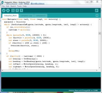
In order to program the AtMegas I used a FT232 chip, and all I had to do was plug it into each circuit and upload the appropriate sketch using the Arduino software (see image above) just like I would with an Arduino Uno. The only difference is that you need to select "Arduino Nano w/ ATmega328" instead of "Arduino Uno" in Tools > Board. The code was very similar to the code used in the third prototype.
The first sketch parsed GPS data and sent it to the second GPS through a serial connection. The sketch would flash the LED on pin 13 when data was being sent, and the LED would glow when there is no GPS lock.
The second sketch has far more responsibility. It takes the current GPS location, calculates the distance from that location to the next waypoint, compares the heading to the next waypoint with the compass bearing, and controls the motors to go there. There's also the override function, which pauses the autopilot while there is a signal from the RC receiver. That signal is then used to calculate the speed of each motor. The waypoints that the autopilot goes to are programmed directly into this sketch.
The second AtMega also needs to calibrate the compass before using it. This is where I switched over to helscream's compass library which does the calibration for me. When calibration is finished, a green LED lights up!
The sketch that I uploaded to each chip was essentially a combination of all my previous sketches.
You can download all source code at the very last step of this Instructable!
Step 11: Separating the Compass


With the third prototype, whenever I turned on the motors, the compass would shift up to ten degrees to the left. Clearly there was some interference. I noticed that this interference got exponentially smaller as I moved the autopilot up the boat, so I decided to simply move the compass forward.
Since the compass is really sensitive to tilt, I decided to build a support for the compass out of foamcore. I used double sided tape to stick this support to the front of the boat, then I placed the compass inside the support. I also created a four wire extension cord for the compass out of scrap speaker wire and some pin-headers. One end of this extension cord went to the compass, while the other plugged into the autopilot. Once again, I used hot glue to insulate these connections.
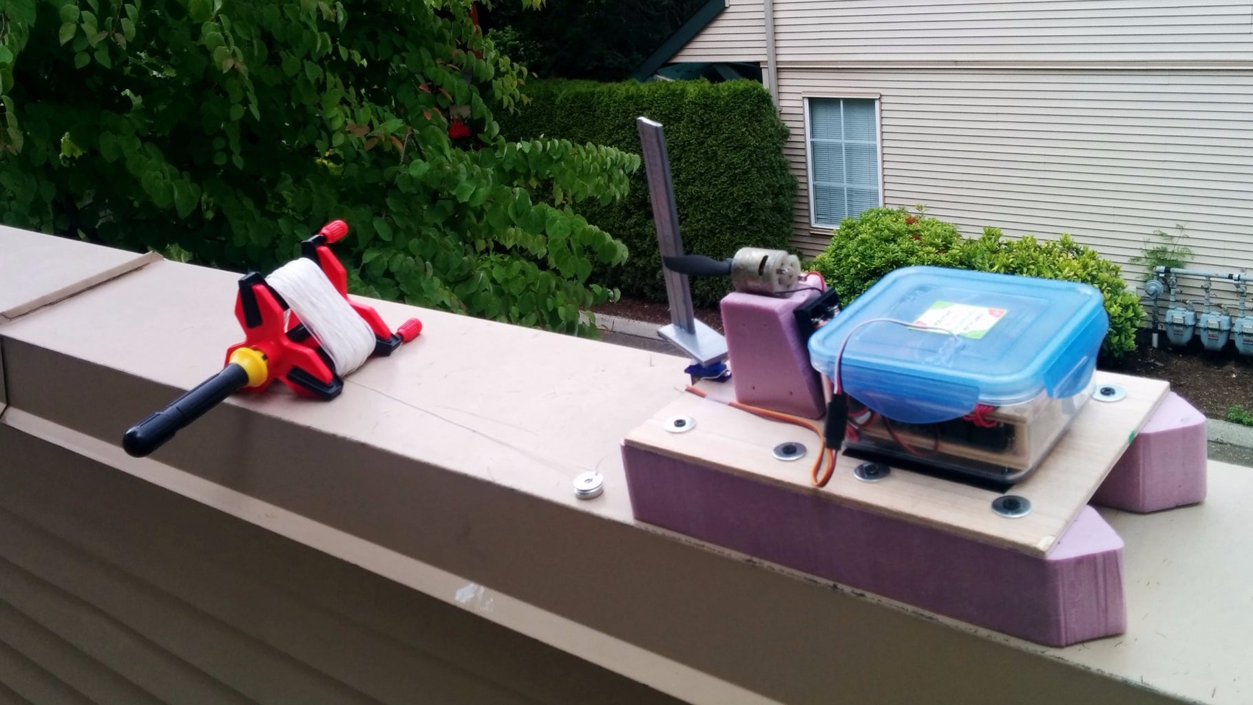
Step 12: Testing the Autopilot


After extensive bathtub testing, it was finally time for a proper real-world test! Once again, I brought the boat to the pond, programmed three waypoints that were in a triangle, used the manual override to steer the boat away from land, and let it rip! The autopilot was able to go to each waypoint in order, and when it was done will all three waypoints it would loop and go to the very first waypoint again! Success!
The autopilot was able to travel to these waypoints at about 30% throttle, which is about walking speed. I set the speed this low because I didn't want the MOSFETs to overheat, and I generally wanted to play it safe.
After the first fully successful triangle test, I spent the next week testing one new path a day. I tried everything from triangles, to circles, to squiggles, to zig-zags, and the autopilot was able to travel the paths just like it was supposed to!
On two occasions, the wire that served as the one-way serial connection between the two AtMegas came loose. Thankfully, I was able to use the manual override to bring the boat to shore, connect the wire again, and send the boat on its way. The GPS signal never got lost during testing, and the battery lasted roughly ten minutes each charge.
Step 13: Next Steps, Final Thoughts and Downloads
Improvements:
This boat is essentially finished, but there is always room for improvement. While doing the last few tests, I noticed that the boat would sometimes begin oscillate after a turn. Turns out, since the compass is not tilt-compensated, there's enough deviation after a turn to start this oscillation. In order to make a compass tilt-compensated you need add an accelerometer, but I thought an easier way to implement one is to buy the GY-511, which is a compass and an accelerometer, and it uses the same I2C protocol as my current compass! When the new chip gets here, all I will have to do it switch some pins around and that's it!
There's also the issue of paths. The program I wrote for this autopilot is very simple, so it doesn't follow a path, or compensate for drift. A PID controller is specifically made to compensate for this, so I'm going to try to implement one in my software.
Also, I have an SD card reader available. I was thinking of implementing it in order to record GPS data, but it seems to run at a lower voltage level.
Downloads:
Just below you can find the source code for my autopilot. The Autopilot_GPS file is for the AtMega chip that is connected to the GPS, and the Autopilot_Main is for that main AtMega. Other files contains previous versions of the autopilot (the first two prototypes). Again, just extract the archives somewhere, and inside are the files that are directly compatible with Arduino software!
Final Thoughts:
I am really happy with not only how this project turned out, but I'm also happy that I learned a lot of really important skills; everything from programming to designing circuits. I think that when I grow up I'll be doing things like this, writing programs, making drones, projects, but obviously on a bigger level.
Also, there's a lot I haven't mentioned in this Instructable. On my blog there's more info about this project, and you'll be able to find my other projects like my weather station, electric longboard, and flying machines!


Participated in the
Move It


