

Introduction: Boot Bot Arduino Bootload Shield


Update: The Boot Bot has been entered into the Arduino Challenge. Please Vote!
Check out this project and others at Revolt Lab
I have entered this instructable in the Shopbot contest! If I win, I will use the Shopbot to make the armor and turret system for my power wheels mobile rocket launcher!
Step 1: Materials


To make a Boot Bot you will need:
breadboard
wires
atmega 328 chip
(2) 22pf Capacitors
(1) 10k resistor
(1) 16 MHz crystal
perfboard
male headers
28 pin IC socket or (4) 8 pin sockets
Step 2: Breadboard the Circuit


Breadboarding the circuit before you solder a final version could save you hours of frustration if you have a malfunctioning part! To test if our components all work we can follow the official arduino bootloading tutorial First, lay out your breadboard and arduino as shown in the image above. Note that the 10k resistor is connected to power and not to ground. The two capacitors are those 22pf capacitors you have ready. Remember that the notch on the end of the chip indicates the left side. See the second picture above for a closer look at the pin map of the atmega 328.
Now before you follow the rest of the tutorial, finish the breadboard and go to the next step!
Step 3: Program the Arduino

Find this cluster...
int error=0;
int pmode=0;
Put this above the cluster...
int initSent=0;
Find this cluster...
  switch (ch) {
  case '0': // signon
    empty_reply();
    break;
Change it to this...
  switch (ch) {
  case '0': // signon
    if(! initSent) empty_reply();
    initSent = 1;
    break;
Thank you to the wonderful people on the arduino forums for helping me solve this problem!
Step 4: Test the Circuit
Upload the ISP sketch onto your arduino.
Insert a raw Atmega 328 into the breadboard.
Select Tools>Burn Bootloader> Arduino as ISP.
The tx and rx LEDs on your arduino board should spaz out for a minute or two while it burns the bootloader.
The IDE will tell you when the bootloader is done.
If your computer says it is done bootloading and you got no error message, congrats! Now that we know it works, we can start soldering!
Step 5: Find the Right Spacing

You will need two strips of male header pins. One strip will be only two pins long. The other will be four pins long.
Insert the two pin strip into the adjoining 5 volt and ground pins on the arduino.
Insert the four pin strip into arduino pins 10, 11, 12, and 13.
Now that your pins are in place, position your perfboard over them to see where they will fit on your perfboard.
It can be helpful to mark the holes you assign to the header pins with a marker.
Step 6: Solder!


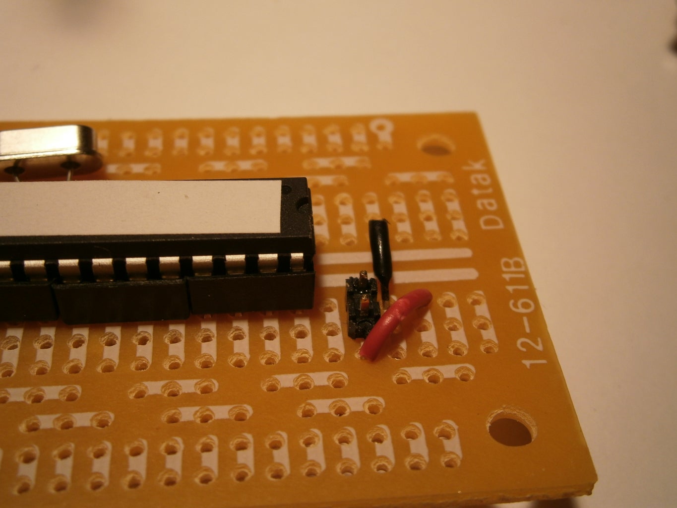


Solder up the perfboard according to the same connections you made on the breadboard in step 2.
I find it helpful to check each connection with a multimeter before I move on to the next solder joint.
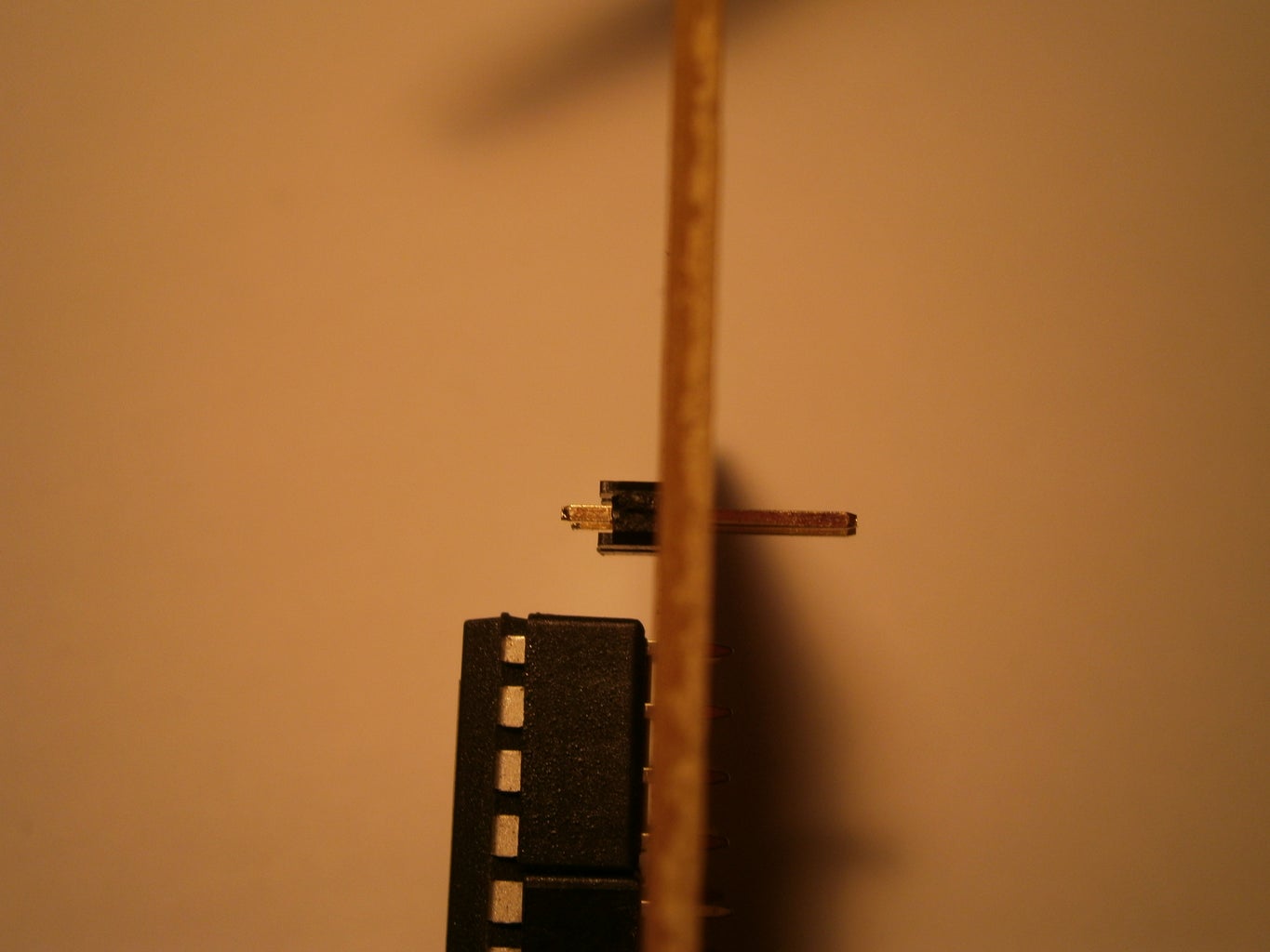
Pushing the male header leads down a bit through their housing can make it easier to solder and have a long enough lead left to hook up to the arduino.
If you use 4 8pin sockets as I did here:
1. Do all soldering with a chip placed firmly in the sockets. This will ensure that none are so askew as to not fit the atmega 328.
2. Solder even the loose socket connections to empty pads on the perfboard. This will ensure the sockets stay in place.
Step 7: Test


Insert a new raw chip into the socket on your new Boot Bot.
Load the ISP sketch onto your arduino.
Attach the Boot Bot shield on top of the arduino.
In the arduino development environment, Select Tools> Burn Bootloader> w/ Arduino as ISP.
Congratulations! You can now give birth to arduinos!

Participated in the
Arduino Challenge

Participated in the
ShopBot Challenge


