

Introduction: Building a DIY Arduino on a PCB and Some Tips for Beginners

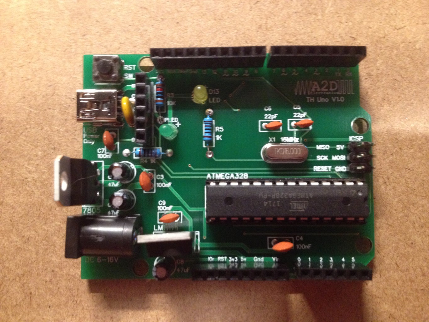


This is meant as a guide to anyone soldering their own Arduino from a kit, which can be purchased from A2D Electronics. It contains many tips and tricks in order to build it successfully. You will also learn about what all the different components do.
Read on and learn what it takes to build your very own Arduino!
You can also view this project on my website here.
Step 1: Mini USB Connector


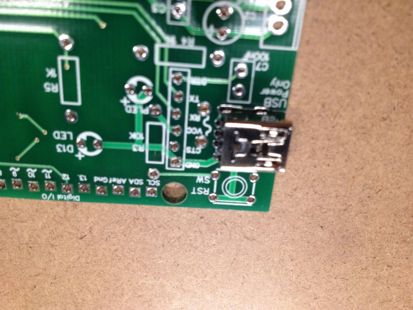
The first part to solder is the mini USB connector. This will provide power to your arduino when completed, but an RS232 / USB to Serial adapter will be needed for programming it. The mini USB socket goes in first so that you can put it in, flip the board over so that the pins are facing upwards, then put it down on the table. Before putting it in, bend the mini set of 2 pins slightly towards the front of the board so that it will fit in the holes on the PCB nicely. The weight of the PCB will hold the connector in place, and you can solder it right there.
Step 2: Pin Headers
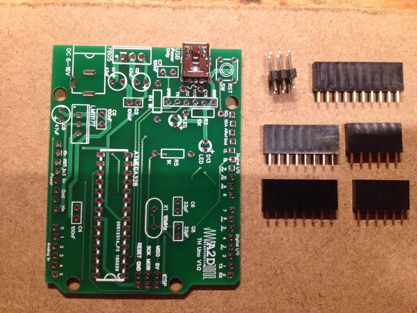
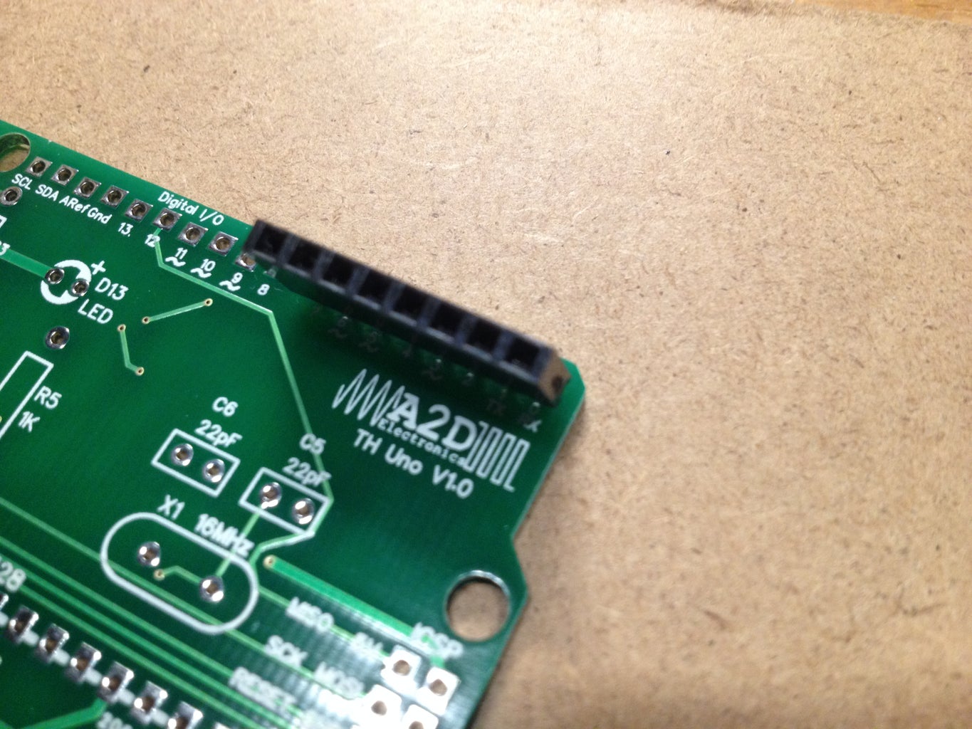
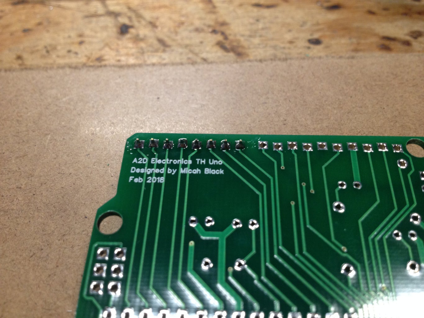
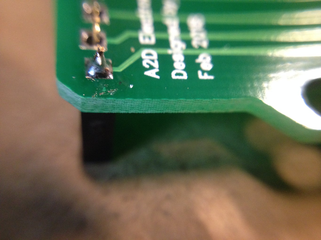
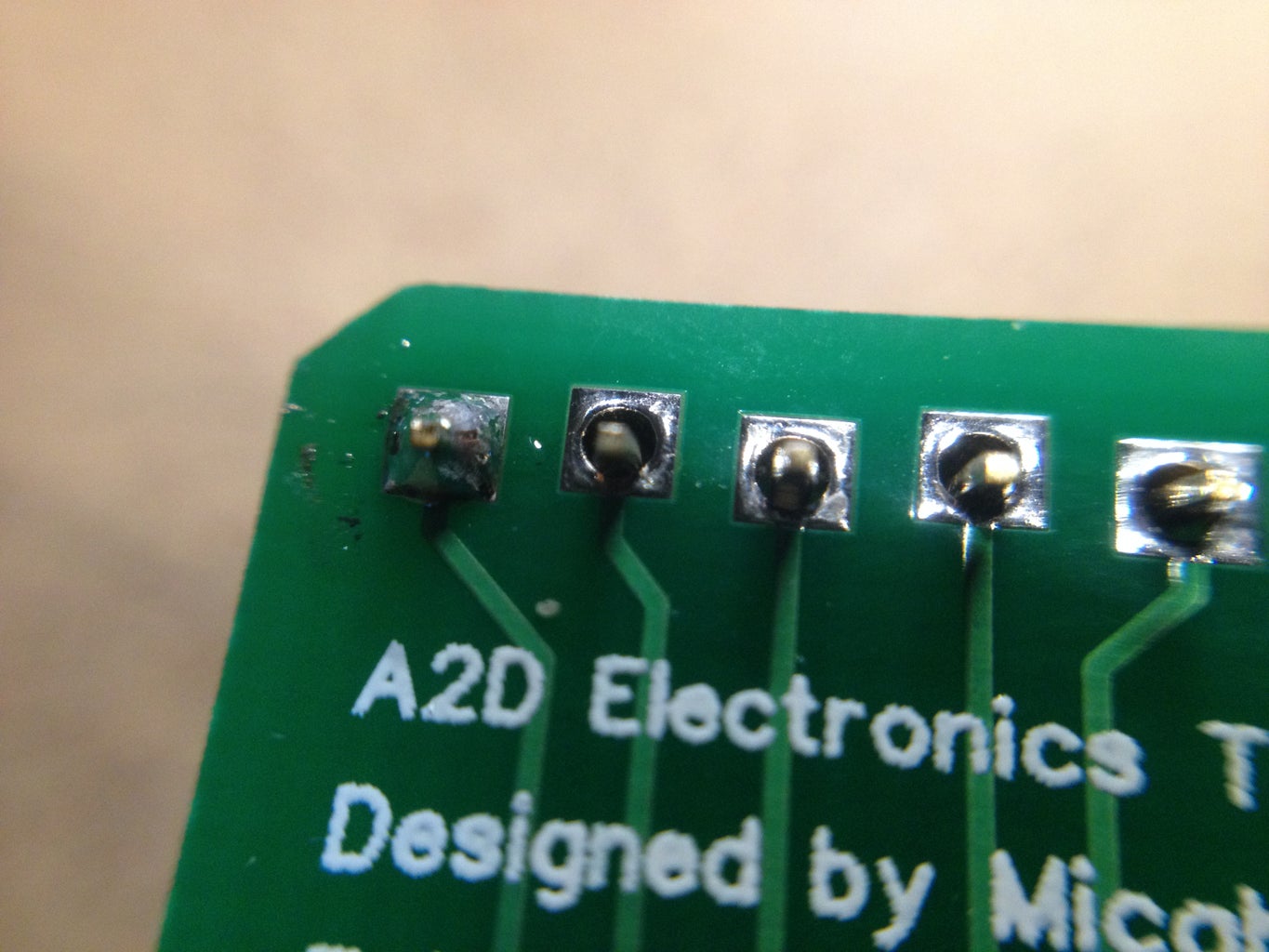
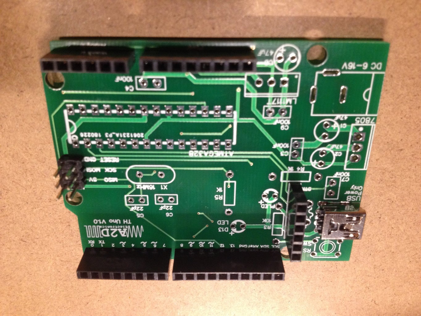

Pin headers are the next pieces to go in. You should have female headers in 6pin x2, 8pin x2, and 10pin x1. A male header of 3×2 is also required for the ICSP (In Circuit Serial Programming) header. These all go around the outside of the board, and will fit perfectly in their proper places. Solder them in with the same method as the USB socket, doing one header at a time. The headers should all be perfectly perpendicular to the PCB. To achieve this, solder only one pin of the header, then while holding the header in with your hand, melt the solder again and reposition the header to its perpendicular position. Make sure that it also sits flush against the board for the entire length. Hold it in position until the solder hardens, then continue soldering the rest of the pins.
Step 3: IC Socket


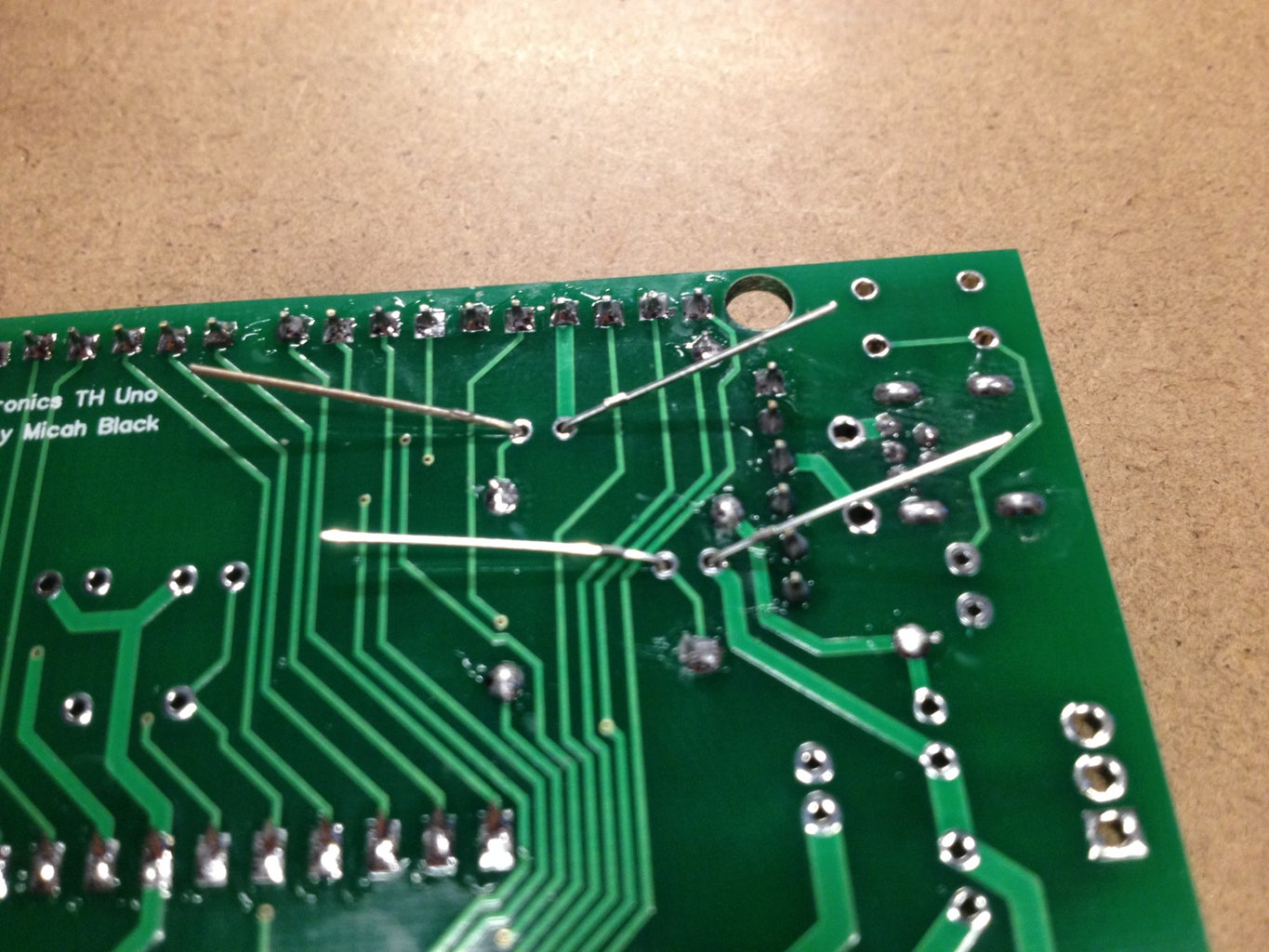
Quick tip for soldering the rest of the components:
All the component leads can be placed through the board first, then bent to the side so that the components will stay in the board when flipping it over. This will make it much easier to solder as the components will hold themselves in place.
Start by placing the 28pin IC socket. Make sure to line up the divot at one end with the drawing on the PCB. This lets you know which way to insert the AtMega328P microcontroller. Even though the pins on this socket are shorter than resistors or capacitors, they can still be bent over to hold the component in place while you are soldering it.
Step 4: Resistors

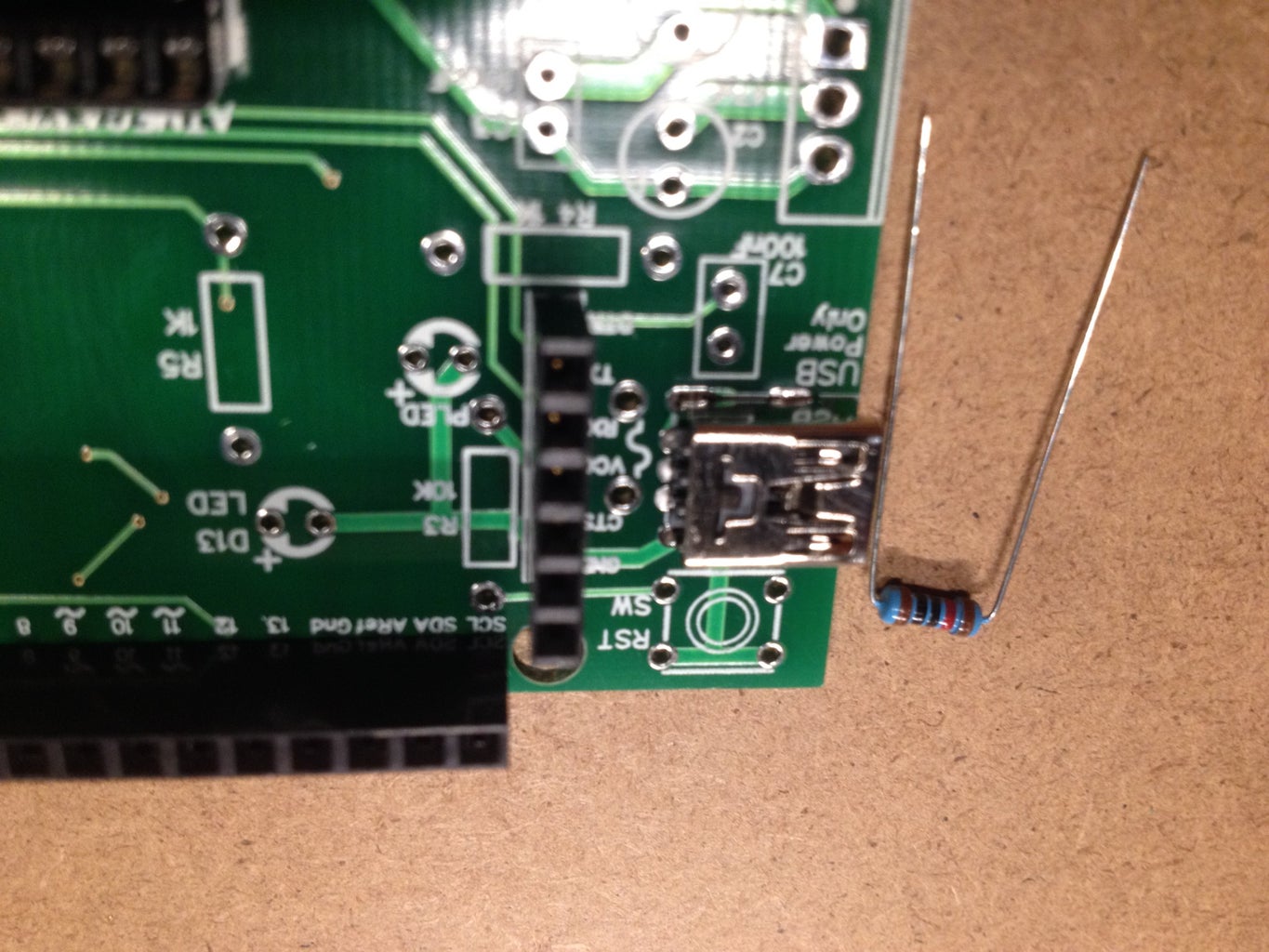


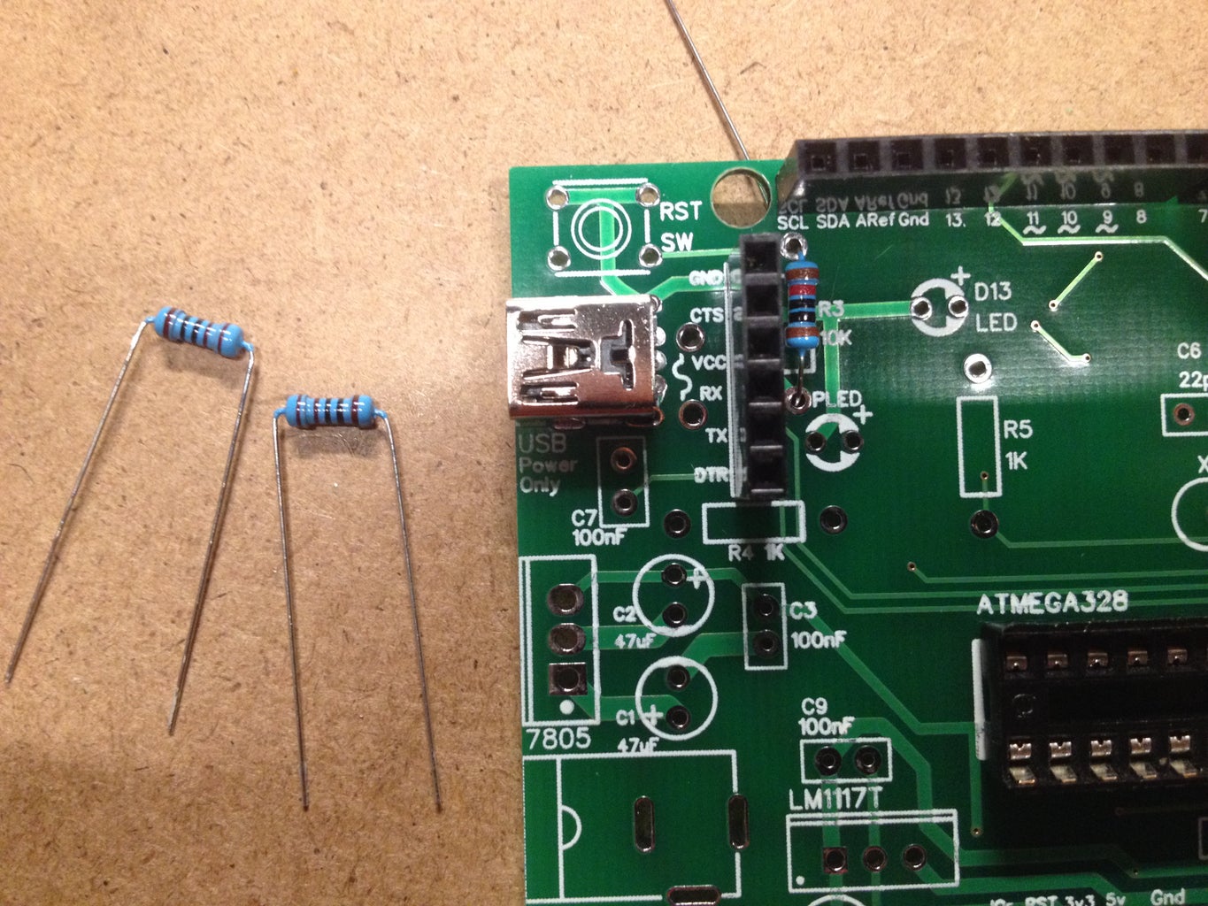


The 3 resistors can go next. It does not matter which way they are placed – resistors are not polarized. There are 2 1K ohm resistors as current-limiting resistors for the LEDs, and a 10K ohm resistors as a pull-up resistor on the reset line. 1K ohm resistors were chosen for the LED instead of the common 220 ohm ones so that the LEDs will have a lower current passing through them, thus acting more as indicators than a flashlight.
Step 5: LEDs
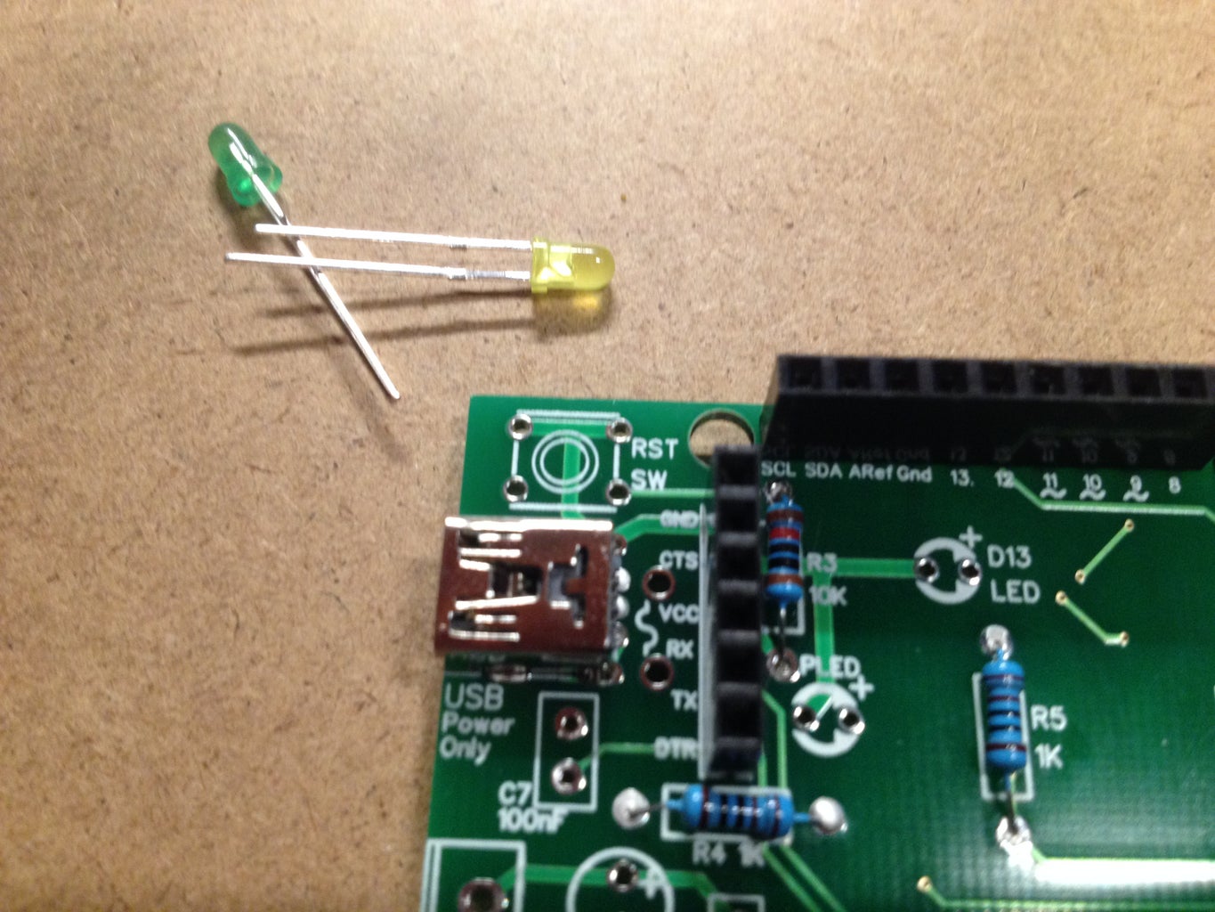
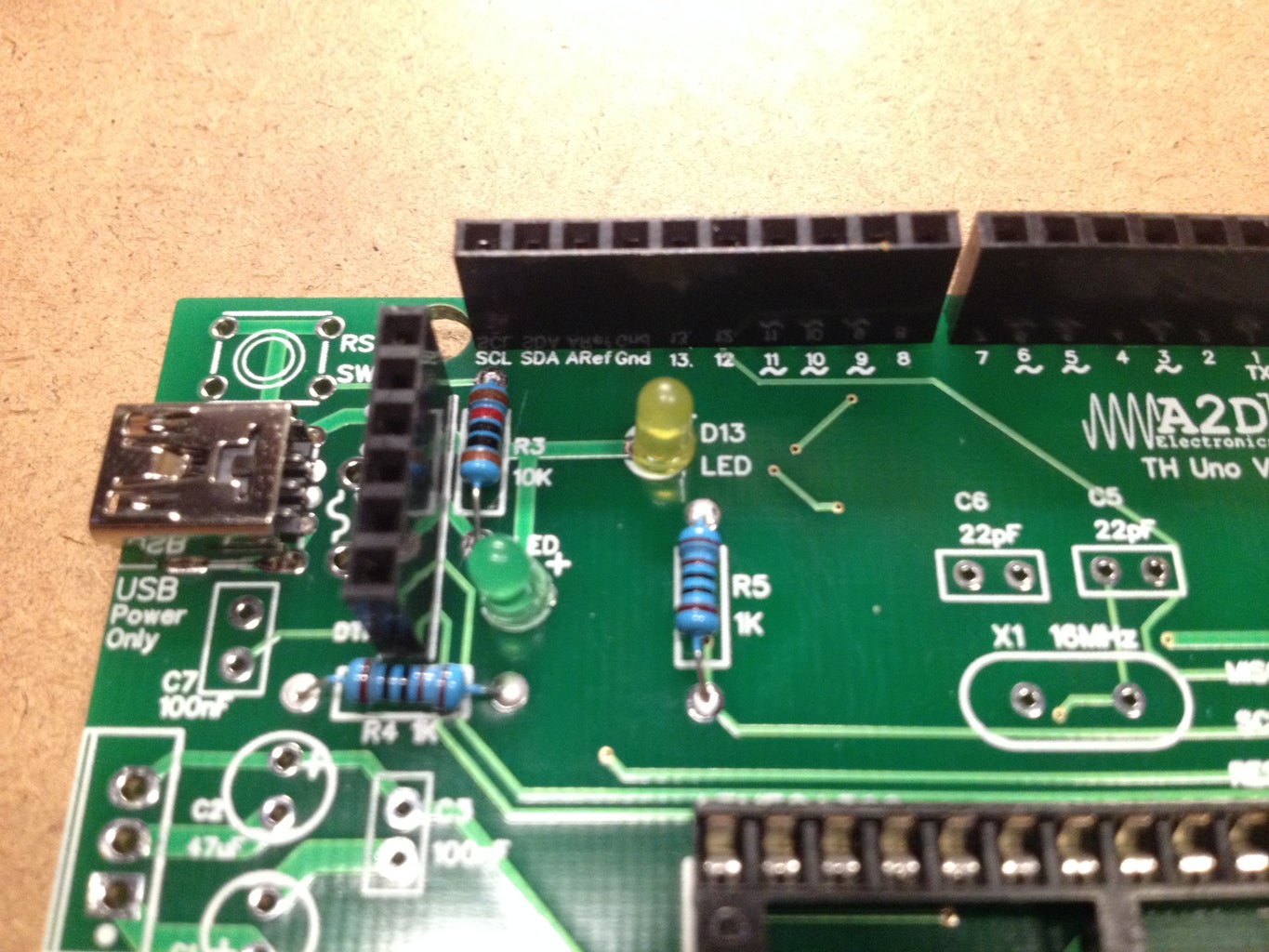
There are 2 LEDs, one as a power indicator, and the other on pin 13 of the Arduino. The longer leg on the LEDs marks the positive side (anode). Make sure to put the longer leg in the side marked + in the PCB. The negative lead of as LED is also flattened at the side, so that you can still decipher positive (anode) and negative (cathode) leads if they were cut.
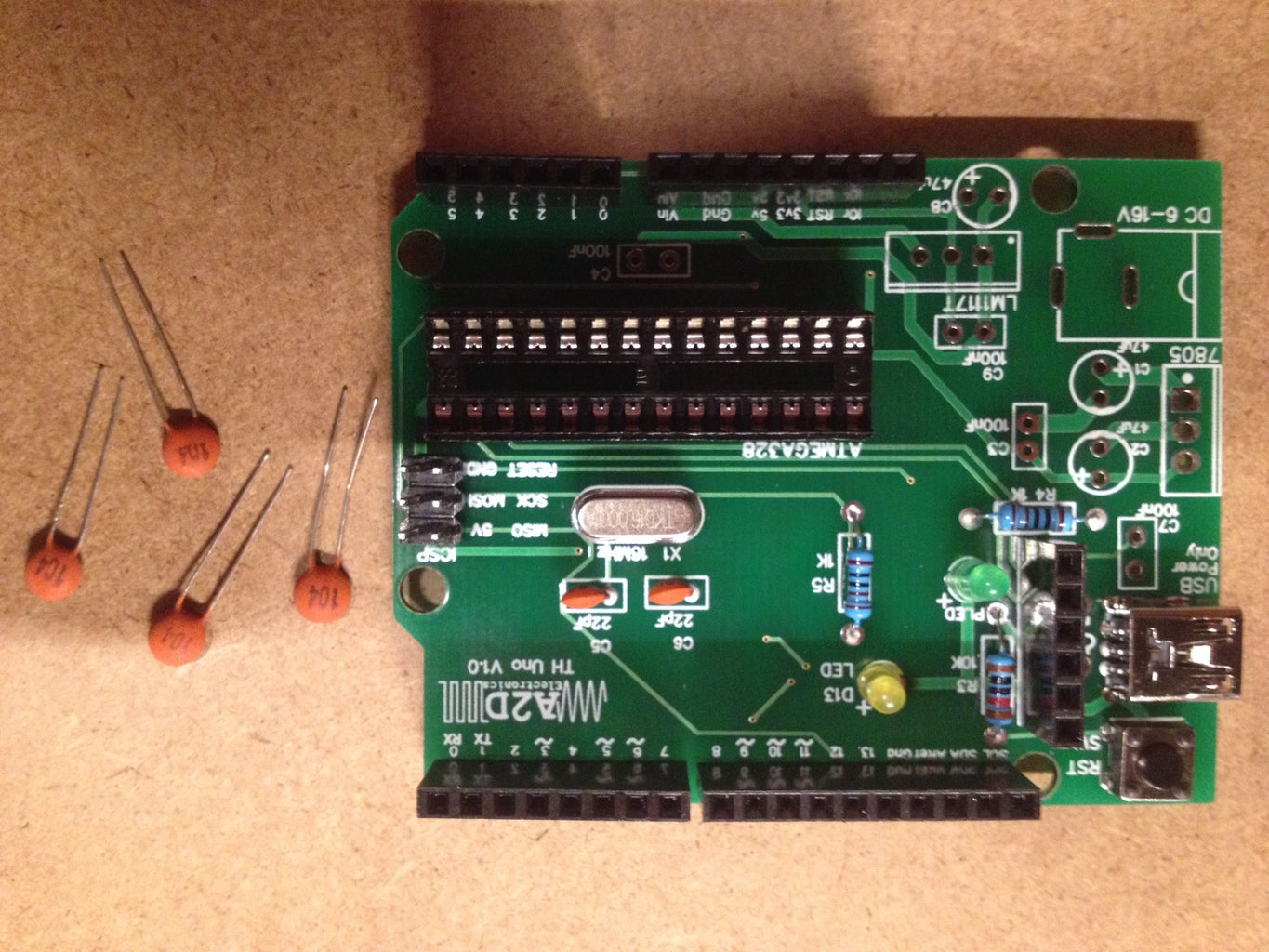
Step 6: Oscillator
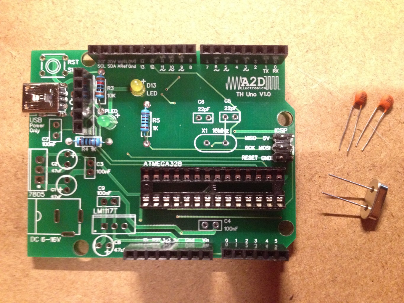

Next up is the crystal oscillator and the 2 22pF ceramic capacitors. It does not matter which way any of these get put in – ceramic capacitors and crystal oscillators are not polarized. These components will give the Arduino a 16MHz external clock signal. The arduino can produce an 8MHz internal clock, so these components are not strictly necessary, but let it operate at full speed.
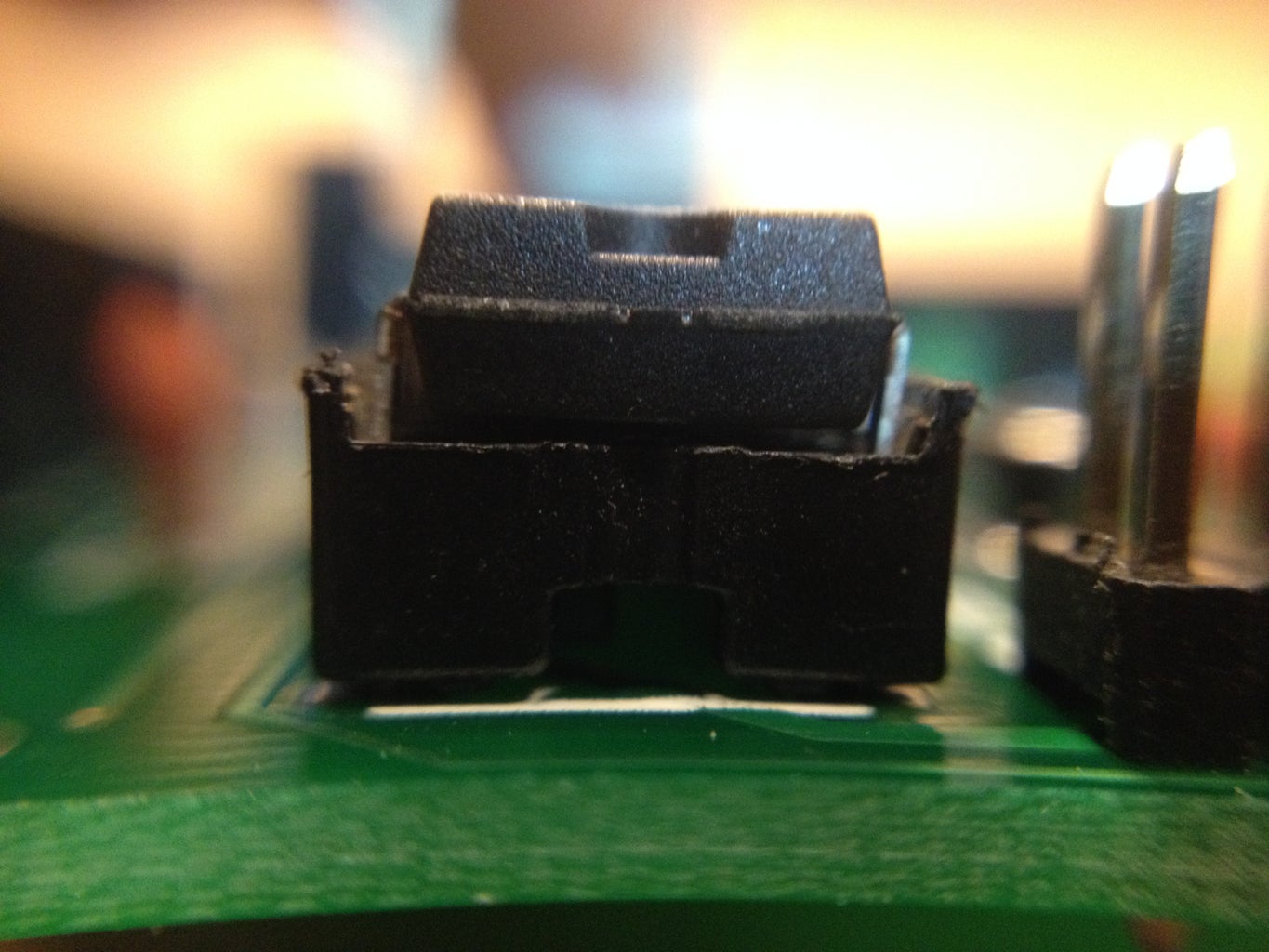
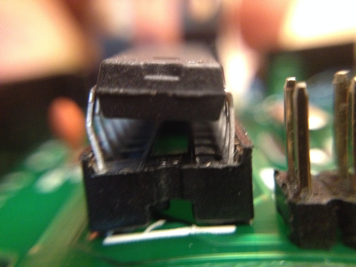
Step 7: Reset Switch

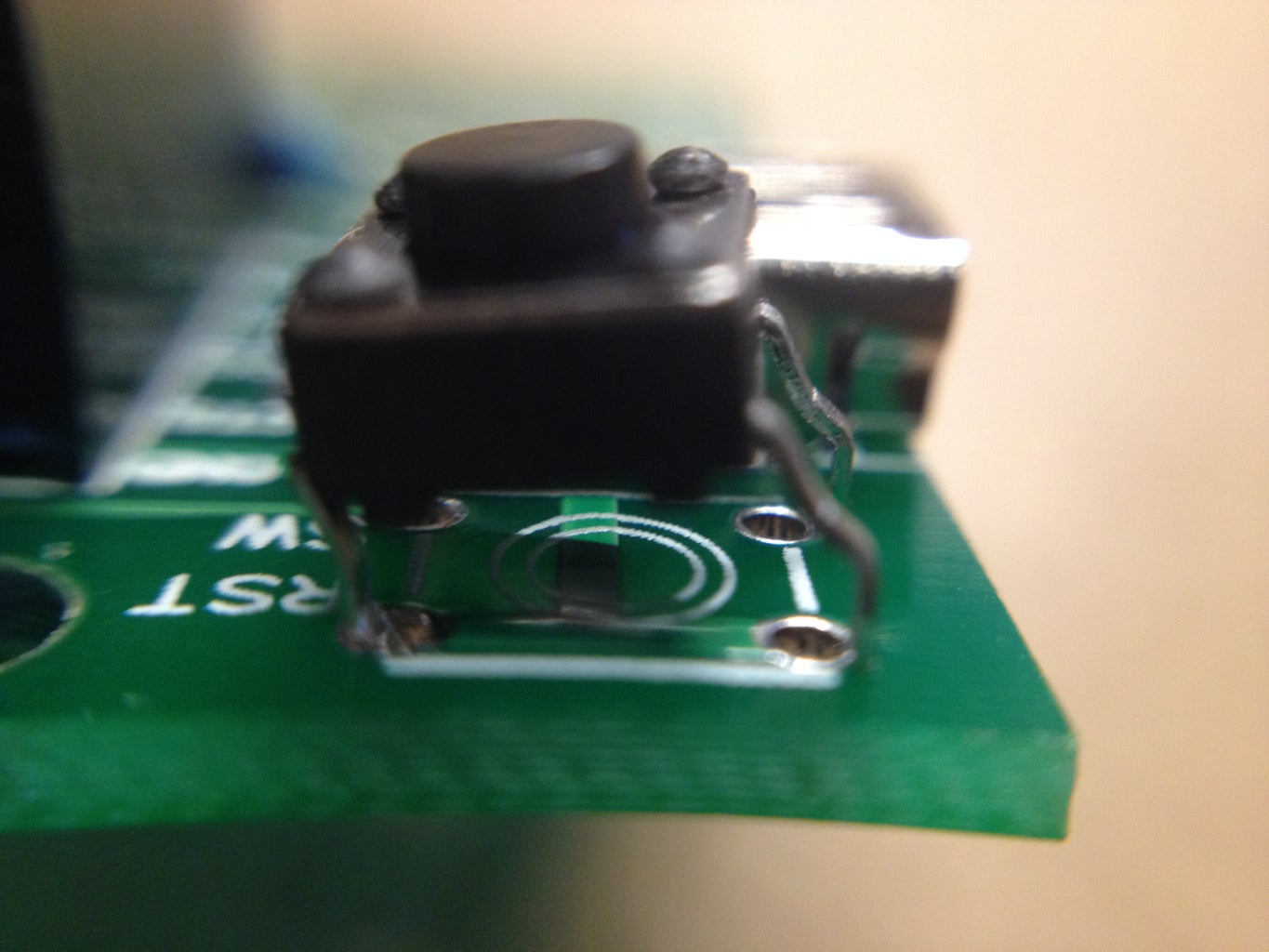
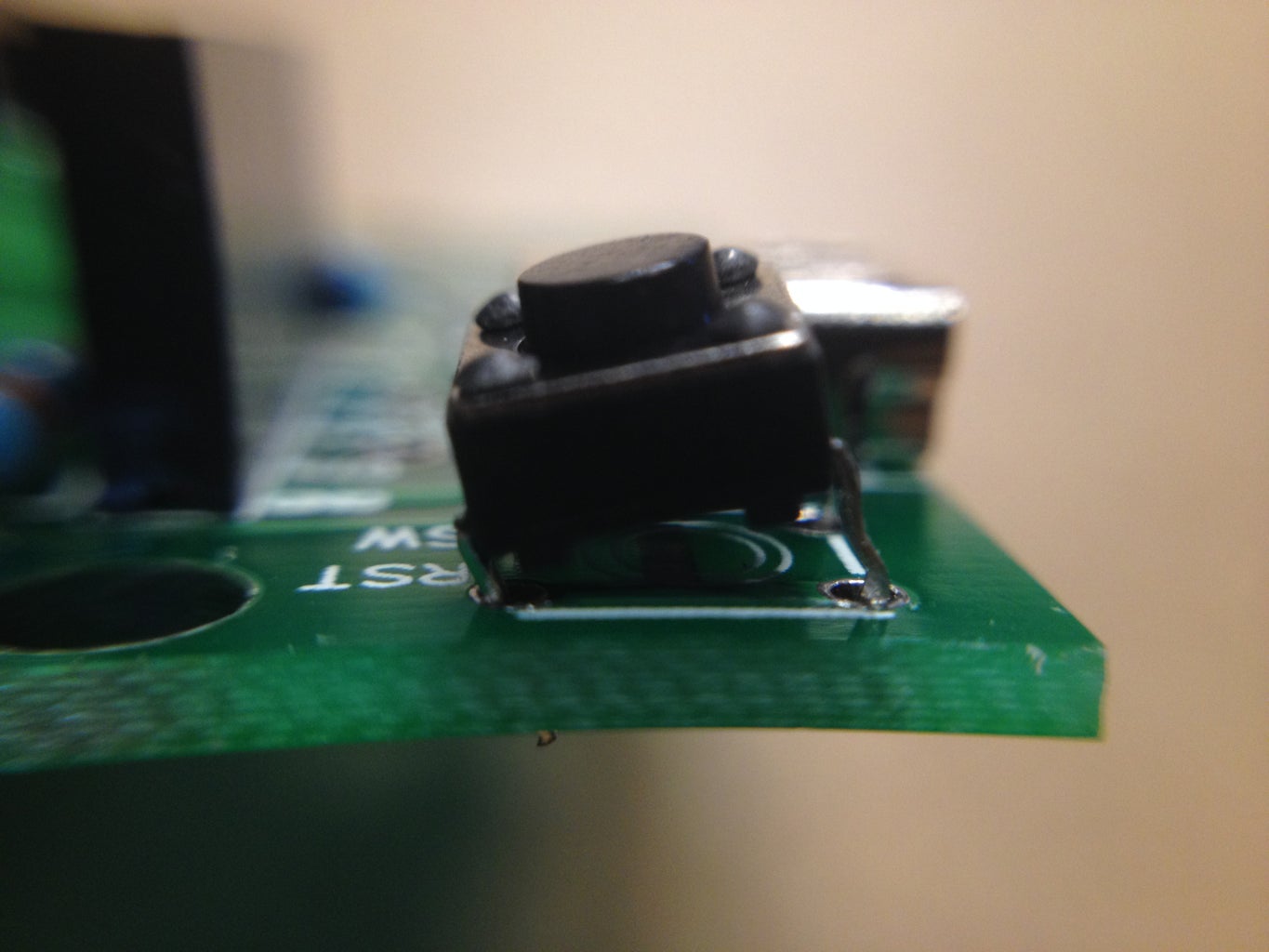


The reset switch can go next. The legs on the switch do not have to be bent, it should hold itself in the slot.
Step 8: Ceramic Capacitors


4 100nF (nano Farad) ceramic capacitors can go next. C3 and C9 help smooth out small voltage spikes on the 3.3V and 5V lines to deliver clean power to the Arduino. C7 is in series with the external reset line to allow an external device (USB to Serial Converter) to reset the Arduino at the right time in order to program it. C4 is on the Arduino’s AREF (Analog Reference) pin and GND to ensure that the Arduino measures accurate analog values on it’s analog inputs. Without C4, AREF would be considered ‘floating’ (not connect to power or ground), and will cause inaccuracies in analog readings because a floating pin will take on whatever voltage is around it, including the small AC signals in your body that have come from the wiring around you. Again, ceramic capacitors are not polarized, so it does not matter which way you put them in.
Step 9: PTC Fuse


Now you can install the PTC (positive temperature coefficient) fuse. The PTC fuse is not polarized, so can be put in either way. This goes right behind the USB socket. If your circuit tries to draw more than 500mA of current, this PTC fuse will start to heat up and increase resistance. This increase in resistance will lower the current, and protect the USB port. This protection is only in circuit when the Arduino is being powered over USB, so when powering the Arduino via the DC jack or by external power, be sure that your circuit is correct. Make sure to pull the legs all the way through the holes, even past the bends. A pair of pliers will be helpful here.
Step 10: Electrolytic Capacitors


The 3 47uF (microFarad) electrolytic capacitors can be put in next. The longer leg on these is the positive leg, but the more common identification is the coloring of the casing on the side of the negative leg. Ensure that when you put them in, the positive leg goes towards the + mark on the board. These capacitors smooth out the bigger irregularities of the input voltage, as well as the 5V and 3.3V lines, so that your Arduino gets a steady 5V/3.3V instead of a fluctuating voltage.
Step 11: DC Jack


Next up is the DC input jack. Same deal as all the other components, put it in and flip the board over on top of it to make it stay in place while you solder it. Bending the legs may be a little difficult, as they are thick, so you can always keep this one in place the same way as the mini USB connector that was soldered earlier. This one will only go in one way – with the jack facing the outside of the board.
Step 12: Voltage Regulators


Now the two voltage regulators. Make sure to put them in the right spots. They are both labelled, so just match the writing on the board with the writing on the regulators. The 3.3V regulator is an LM1117T-3.3 and the 5V regulator is an LM7805. Both of these are linear voltage regulators, meaning the input current and the output current will be the same. Say the input voltage is 9V, and the output voltage is 5V, both at 100mA of current. The difference in the input and output voltages will be dissipated as heat by the regulator. In this situation, (9V-4V) x 0.1A = 0.4W of heat to be dissipated by the regulator. If you find that the regulator gets hot during use, that is normal, but if drawing a large current and there is a big voltage difference, then a heatsink on the regulator might be necessary. Now to solder them onto the board, the metal tab on one side should go towards the side on the board that has a double line. To secure them in place until you solder them, bend one leg on one way and the other two the other way. Once soldered in place, bend the 5V regulator towards the outside of the board and the 3.3V regulator towards the inside of the board.
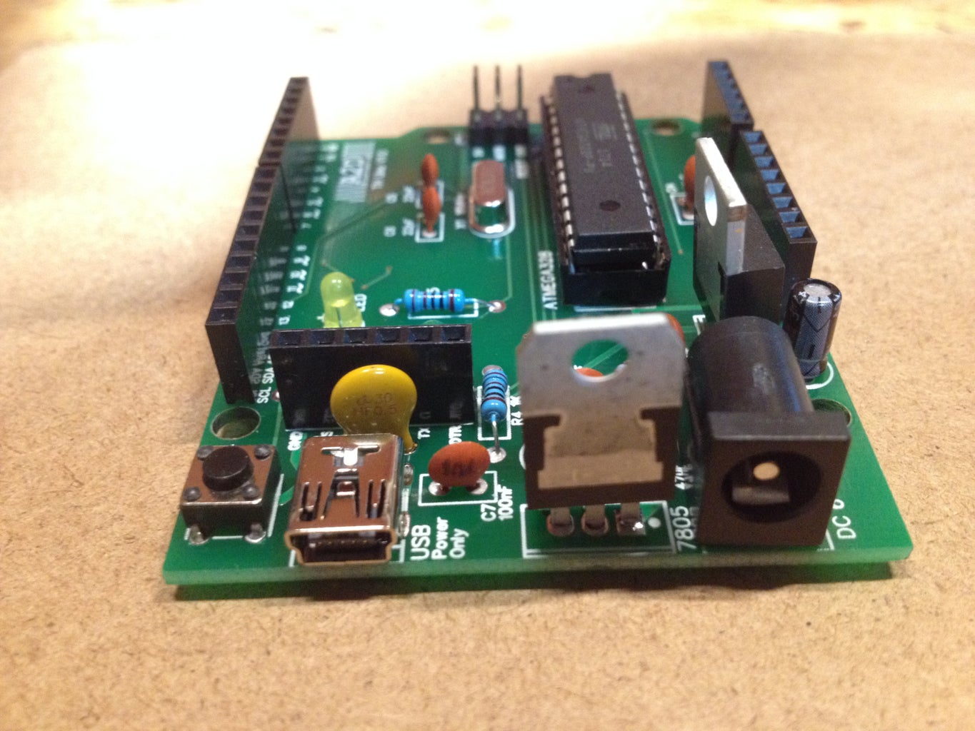
Step 13: Inserting the AtMega328P IC


The final part is to put the microcontroller in its socket. Line up the divots in the socket and on the IC, then line up all the pins. Once in place, you can push it down. It will take a bit more force than you might expect, so be sure to apply pressure evenly so that you don’t bend any of the pins.
Step 14: A Few Notes of Caution With Your Arduino
- NEVER connect USB power and external power to the Arduino at the same time. Although these may both be rated at 5V, they are often not exactly 5V. The small voltage difference between the two power sources causes a short circuit through your board.
- NEVER draw more than 20mA of current from any output pin (D0-D13, A0-A5). This will fry the microcontroller.
- NEVER draw more than 800mA from the 3.3V regulator, or more than 1A from the 5V regulator. If you need more power, use an external power adapter (a USB power bank works well for 5V). Most Arduinos generate their 3.3V power from the USB to Serial chip on board. These are only capable of a 200mA output, so if you use a different Arduino, make sure that you’re not drawing more than 200mA from the 3.3V pin.
- NEVER put more that 16V in the DC jack. The electrolytic capacitors used are rated for only 16V.
Step 15: A Few Tips / Interesting Facts
- If you find that your project needs lots of pins, the analog input pins can also be used as digital output pins. A0 = D14, up to A5 = D19.
- The analogWrite() command is actually a PWM signal, not an analog voltage. PWM signals are available on pins 3, 5, 6, 9, 10, and 11. These are useful for controlling the brightness of an LED, controlling motors, or generating sounds. To get an audio signal on the PWM output pins, use the tone() function.
- Digital pins 0 and 1 are the TX and RX signals for the AtMega328 IC. If possible, do not use them in your programs, but if you must, you might need to unplug the parts from those pins while programming the Arduino.
- SDA and SCL pins for i2c communication are actually pins A4 and A5 respectively. If using an i2c communication, pins A4 and A5 cannot be used for other purposes.
Step 16: Programming Your Arduino
First unplug any external power to avoid shorting out 2 different power supplies. Now attach a USB to Serial adapter to the header just behind the mini USB power. Connect it up according the following:
Arduino USB to Serial adapter
GND GND (ground)
VCC VCC (power)
DTR DTR (reset pin)
TX RX (data)
RX TX (data)
Yes, the TX and RX pins do get flipped. TX is the transmitting pin, and RX is the receiving pin, so if you had 2 transmit pins connected together, not much would happen. This is one of the most common pitfalls for beginners.
Make sure the jumper on the USB to Serial adapter is set to 5V.
Plug the USB to Serial adapter into the computer, select the appropriate COM port (will depend on your computer) and Board (Arduino UNO) in the Tools menu of the Arduino IDE (downloaded from Arduino.cc), then compile and upload your program.
Step 17: Testing With a Blink Sketch
The first thing you should do is to blink an LED. This will familiarize you with the Arduino IDE and programming language, and ensure that your board is working properly. Go to the examples, find the Blink example, then compile and upload to the Arduino board to make sure that everything works. You should see the LED attached to pin 13 start to blink on and off at intervals of 1 second.

Participated in the
Microcontroller Contest


