

Introduction: Building a Model for Satellite-Based Laser Communication


We're two students and built this model for our course Empirical Evidence in Engineering, but it also relates to our larger semester project, which is about using lasers for communication between Mars and Earth. We'll start off with some background information:
With a possible Mars mission in the near future, improving communication technology will become necessary. Lasers are much more efficient than radio frequencies, which are commonly used nowadays. The increased efficiency is mainly achieved through smaller divergence and a narrower beam. This makes pointing the laser challenging. Over a large distance, a minute change in angle will cause a large offset at the receiving satellite. The satellites are not entirely stable; they vibrate due to internal systems and external influences. To avoid losing the connection because of these vibrations, a complex pointing system is required [read more].
Before the satellites are connected for the first time or after losing connection for a longer period, the signal has to be (re-)acquired. The general area in which the satellite can be found is known. A search pattern is executed in that area until the receiving satellite is found and returns confirmation of receiving the laser beam. What we'll be building is a small-scale model of two satellites. A laser, moved by two servo motors, will try to find a target based on information sent back from the target. The target senses the laser beam with photocells. An Arduino will adjust the laser positioning and execute search patterns to find the target.
Step 1: Assemble Your Materials


Here's a list of the stuff we used:
- a laser
We ordered ours from amazon. It was a small (10mm x 22mm) laser with a wavelength of 650nm. At 0.75mW and a voltage between 3 and 12V DC, a 9V battery can be used to power it. - a 9V battery + fitting snap connector
to power the laser - five photocells
The standard model that comes up when you google photocell - five resistors (10k Ohms 5% or see picture)
- two servo motors
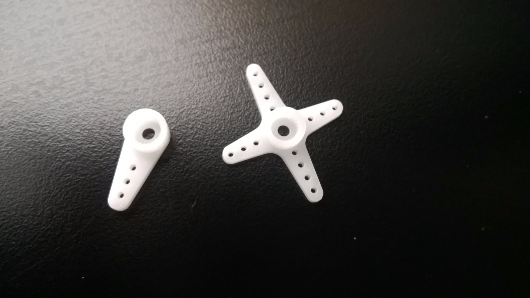
Small servos that can be connected to an Arduino breadboard. - that small plastic part that comes with the servo
We will need this to connect the servos to the platform and the laser, you can see what I mean on the picture of the laser. - an Arduino + the USB cable to connect it
- two breadboards
One right next to the Arduino, the other for the photocells at the target. - a lot of wires
We used a lot of short ones to connect everything on the breadboard and six longer ones (3 m) to connect power and the five photocells to the Arduino. - plywood (4 mm thick)
in combination with access to a laser cutter - a glue gun
Used to put the photocells in place and stick the plywood frame together.
To handle the wires, a wire stripper is useful, but it could also be done without.
Step 2: Lasercutting and Assembling the Framework


We built the framework for the target and the laser platform from laser cut plywood. Using CorelDraw, we made blueprints (attached) and then took them to the laser cutter. The blueprint has to indicate which lines have to be cut and which lines have to be engraved in the wood. Red lines are used for cuts, black lines are used for engravings.
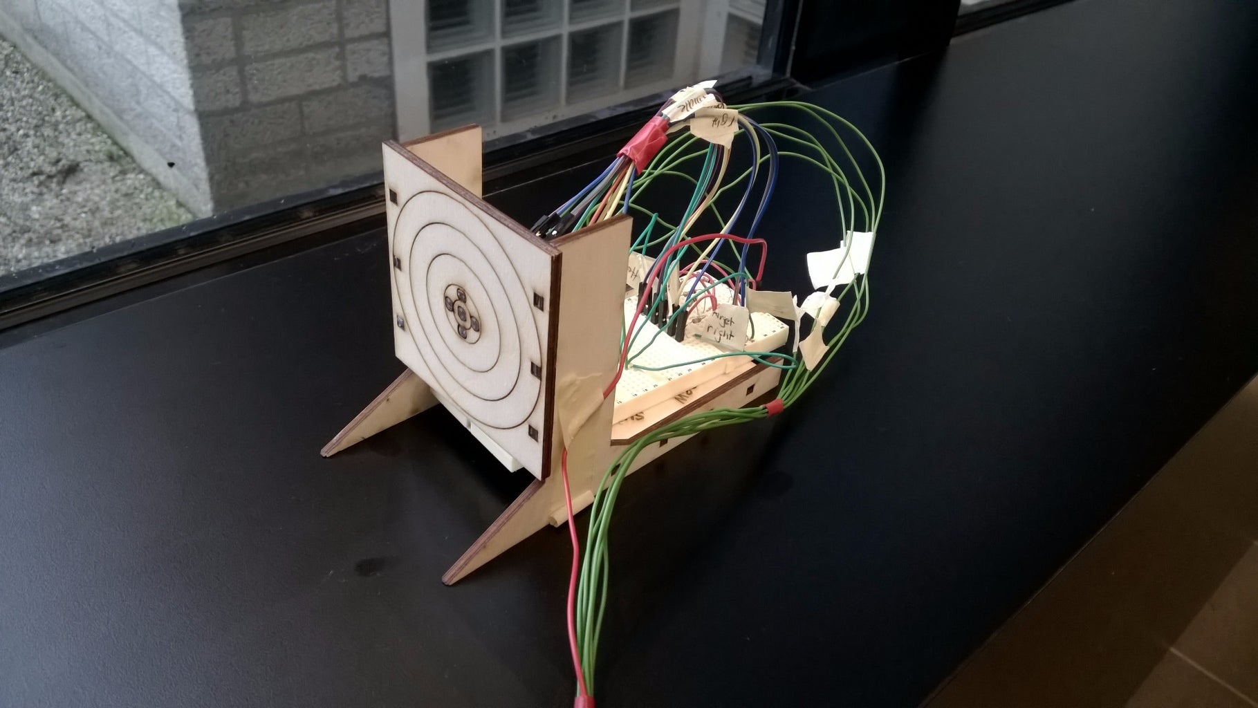
The target consists of a front in which five photocells are placed. On the pictures, you can see that we cut the holes so they would fit the photocells, then used hot glue from the back to fix them to the wood. Two stands hold up the target plate and another plate stabilises the setup from behind.
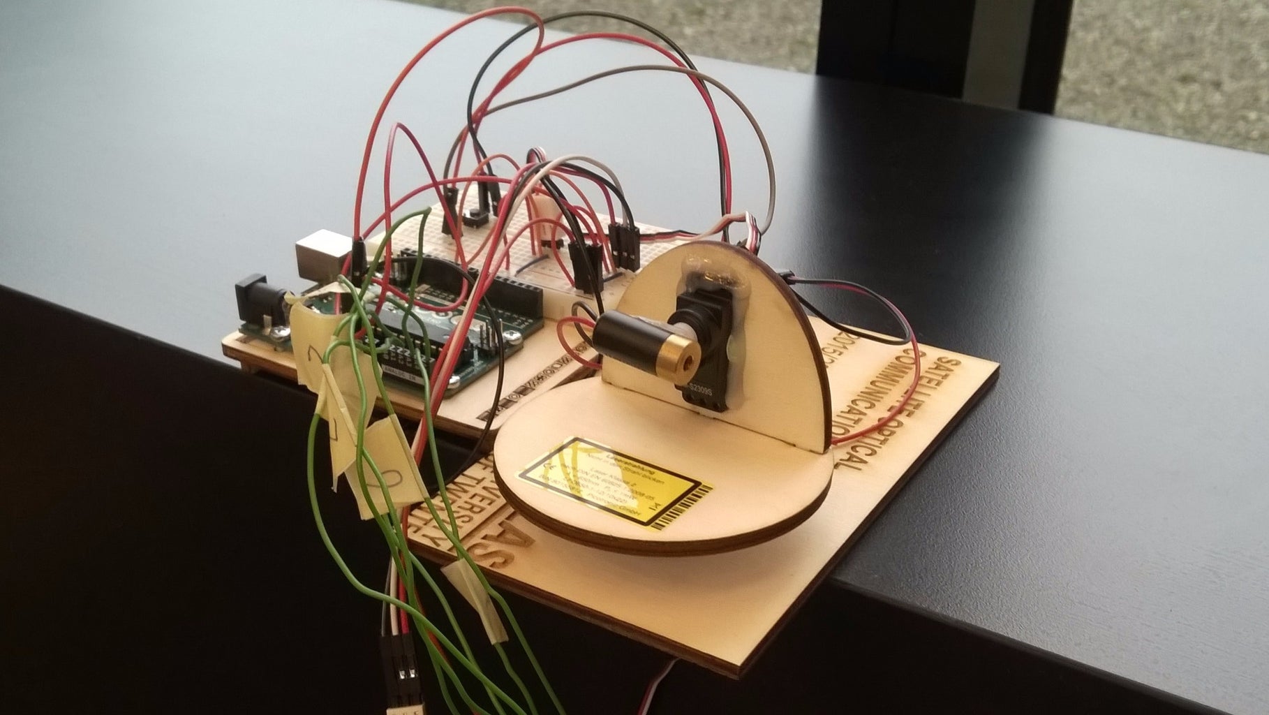
To move the laser, it is connected to a servo that can rotate it vertically. That servo is then mounted to a platform that can be moved horizontally by another servo. We constructed the platform in a way that the vertical axis of rotation is centered on the horizontal axis.
The laser cut pieces can be assembled by sliding the pieces into each other with the pre-cut holes and extensions. Hot glue was then used to stabilise the connections and fix the servos to the platform.
The servos usually come with small plastic connectors that we glued to the laser and to the round platform to connect the different parts of the laser setup.
The file we are providing does not have any text in it, but as you can see in some of the pictures, we added some "personalisations" to ours. This can easily be done by adding text or pictures to the CorelDraw file in black.
Attachments

Step 3: Building the Circuit


Laser diode
The laser diode is powered by a 9 V battery, which is within the 3-12 Volt domain that our laser needs to function. The laser diode is connected to the plus and minus side of the battery and separate from the remaining electrical components.
Arduino
The main circuit consists of five photocells and two servo motors that are connected to an Arduino. No external power sources are used, everything is powered by the Arduino. One of the servo motors is used to rotate the laser diode horizontally, the other moves it vertically. Each of the servos has three connections. The red one has to be connected to power, the black one to ground and the third one (usually white) should be connected to the input pin. We are using pins 9 and 10. When using the code we provide in the next step, the servo in the horizontal direction should be connected to pin 9 and the vertical one to pin 10. It is important to use pins 9 and 10 for this since they are the only ones with PWM output and they are supported by the Servo library we are using.
The five photocells have to be connected to the analog input pins of the Arduino (A0 to A5). One leg of the photocell is connected to power, the other, with the resistor in between, is connected to ground. A cable should connect from between the resistor and the photocell to one of the analog input pins A0 to A5. This will function as a voltmeter, outputting a higher voltage when the laser hits the photocell and the resistance decreases.
Step 4: Programming the Arduino

Photocells
As described previously, both the photocells and the servos were connected to the same Arduino. The Arduino was then programmed to read input from the photocells. The Arduino outputs integer values between 0 and 1023 for different brightnesses. The code has a variable for the threshold. This should be set by measuring the photocell output for background light and with the laser pointing to it. We ended up using values between 200 and 900, depending on how fast the laser moved and how much light there was in the room we were using.
Servos
The servos can be moved by writing a value between 0 and 180, which equals their full range of 180 degrees. Depending on which photocells surpassed the threshold, the servos will adjust the laser positioning to remain pointed to the target.
Make sure to check in what direction the servos spin. In our case, the horizontal servo was at position 0 in the far left and at 180 in the far right. The vertical servo was at position 0 at the top and at 180 at the bottom. If this is different, the code should be adapted for the servos to still move the laser as expected.
Two main mechanisms were implemented:
1/ Small Adjustments
Firstly, the photocells that surround the actual target cause the servos to move the laser in the direction of the target, e.g. if the right photocell is hit by the laser, it will move to the left.
2/ Search Patterns
The second mechanism are different search patterns. If no photocell detects the laser and there is also no information about previous contacts with photocells stored, the laser will begin to execute a search pattern. The first search pattern that was implemented simply scanned a square in which the target was expected to be by sweeping up and down, slowly moving sideways while doing so.
The second search pattern is more sophisticated: It begins scanning in the centre of the square area, then spirals outwards until it has covered the full area. The main advantage of this is that the search begins at the location with the highest probability to find the target. Another difference to the first search algorithm is that this search pattern adjusts the area it scans every time the laser connects to the target: These coordinates are then set as the new centre of the search area should the signal be lost. Both search patterns restart if the target is not acquired after the area has been covered.
Below are illustrations of both search patterns and two Arduino code files that run the system with each of the search patterns.
Step 5: Try It Out!
Now that everything is stuck together, you only have to connect the Arduino, upload the code and watch it do its thing!
For us, a distance of about 1m between the target and the laser worked quite well. Since the servo is sticking out from the bottom plate of the laser mount, you either have to find a table with holes in it (which we conveniently did) or just place it on the edge of a table. It should stay where it is, but you could use a clamp to fix it to the table.
Experiment a bit with different thresholds, distances and the amount of light in the room until you find a setting that works.
Step 6: Optional: Improve It
The model in its current form makes a good effort at modelling the laser link, but could be improved in order to make it work better and also more realistic (since we are trying to model actual satellites here). Here are a few ideas:
- use a different type of motor or introduce gears to have a smaller step size: this would probably make it miss the target less often and it could be run faster
- enlarge the photocell array: this would also make the whole process a lot faster, also you could investigate how large of an array is needed for reasonable acquisition time
- use photosensors that measure only the laser wavelength: we could get rid of the contrast issue with surrounding light vs. laser light
- find a better method for fixing the photocells to the frame: we suspect the hot glue of damaging at least some of the sensors
- try new search patterns: use your Arduino skills to program more search patterns or improve the two we made

Participated in the
Arduino All The Things! Contest


