

Introduction: CARduino - Arduino-Powered, LabVIEW-Controlled Vehicle


The CARduino is a remote-operated vehicle which is controlled by a controller attached to a computer running LabVIEW. The vehicle is powered by the Arduino, and can be expanded upon through the addition of sensors or other devices. Using LabVIEW, one can easily modify the controller program and expand the features of the CARduino with very little or no programming experience.
Two different versions of the vehicle will be covered in this Instructable. The first is a wireless Xbee-equipped version, and the second is a tethered, wired version.
The tethered version is slightly cheaper and is suitable for little more than demonstration purposes, but it's still a fun project. Additionally, the tethered version could be upgraded in the future to support wireless communication.
This Instructable assumes that the reader has at least basic knowledge of circuits and electronic construction.
Because you may use different controllers or Arduino boards, you may have to alter the LabVIEW program or VI (Virtual Instrument). To do this, it may be necessary to learn the basics of LabVIEW.
Step 1: Recommended Reading
Before we get started, it may be important to familiarize yourself with a few things. Skip this step if you're comfortable with everything.
Getting Started With LabVIEW - http://www.ni.com/pdf/manuals/373427c.pdf
Configuring XBees - https://www.instructables.com/id/Changing-Xbee-Baud-Rates/
Step 2: What You'll Need
~Software
-Arduino IDE - http://arduino.cc/en/Main/Software
-LabVIEW - http://www.ni.com/labviewse/compare/
-LabVIEW Interface For Arduino Toolkit - http://sine.ni.com/nips/cds/view/p/lang/en/nid/209835
-X-CTU for wireless version -
~Electronics
-Arduino or Arduino-compatible
-L298N Motor Driver Module (or Arduino Motor Shield)
-Wire
-FTDI-USB Dongle or similar (with required driver software)
-Battery
-Motors (2) with wheels
-Game controller with associated USB adaptor if applicable
~~Wireless Version
-XBee Module (2)
-XBee Breakout Board
-10uF Capacitors (2)
-20K Resistor
-10K Resistor
-LM117 3.3V Regulator
~~Tethered/Wired Version
-Long USB female-male cable
~Body
-Various hardware and scrap metal (or an RC car body)
-Caster
~Tools
-Soldering equipment
-Wire Strippers
-Wire Cutter
-Drill and/or Dremel with appropriate bits and taps for building the body (May not be necessary if an old RC car chassis is used)
Step 3: Program the Arduino
To allow LabVIEW to communicate with the Arduino, you will need to upload the LIFA_Base firmware to the Arduino. This is included with the LabVIEW Interface for Arduino Toolkit.
Step 4: Vehicle Circuit


Both the wireless and tethered circuit diagrams are shown below.
I used a Boarduino instead of a standard Arduino. It is still 100% compatible with Arduino microcontrollers. If you are using an Arduino with a motor shield or an XBee shield, you may need to omit some of the circuit above.
Step 5: Battery Pack

The power source is a 12V battery pack. A single 12V battery could also be used. Just make sure your battery can supply enough current to power your motors. The battery pack in my particular design is made from ten 1.2V rechargeable AA batteries. (10*1.2V=12V)
To make a 12V battery pack from 1.2V cells, they must be connected in series as shown in the picture. If building a pack from ten 1.2V cells, ensure that they all have the same capacity. Higher capacities will allow your CARduino to drive longer without needing to recharge it.
Step 6: Body


The vehicle's body can be assemble from scratch using scrap materials or a discarded RC car body. The body of my particular design is a roughly triangular piece of sheet metal bolted onto a T-shaped frame of 80/20 aluminum extrusion. Two other pieces of metal were bolted to the frame to provide a place to attach the caster.
The drive motors will be mounted at the front of the body. In my case, I used hose clamps to hold my motors in place. I put a small piece of rubber between the clamps and the motors to prevent slipping, and tightened the hose clamps. You may wish to use other means to secure your motors or you might not have to if they're already built into an RC car chassis. At the back of the vehicle, I used a caster to allow for maximum maneuverability.
Next, you will probably want to put some standoffs on the body to mount the Arduino and circuit boards. You will also need to mount your battery on the vehicle. I was able to fit my battery pack under the circuit board. I used four neodymium magnets to hold it in place.
Step 7: Transmitter
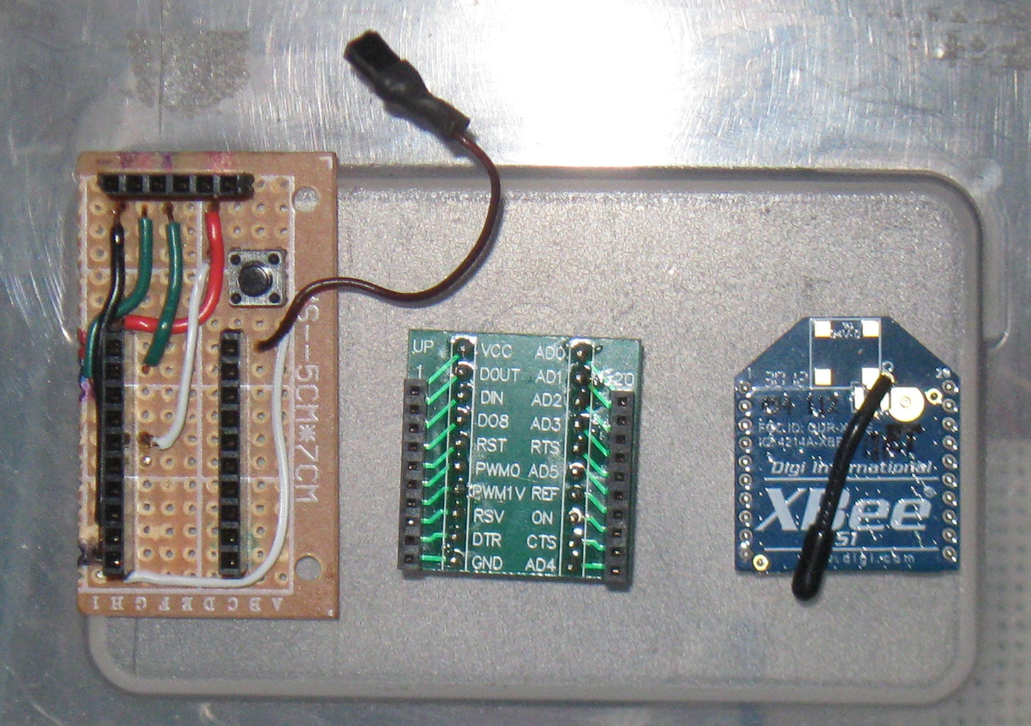

For the wireless version, a transmitter must be built. This transmitter will be connected to the computer running the LabVIEW VI.
This transmitter can be replaced with a similar device such as an XBee Explorer.
I built my transmitter on a piece of perfboard, using female headers to plug the FTDI dongle into, as well as to provide a socket for the XBee breakout board.
Step 8: XBee Configuration
You may skip this step if building the tethered version.
To achieve the automatic resetting of the Arduino with an XBee, we will use IO line passing. The transmitter XBee and the receiver XBee will have to be configured for this.
First, set both XBees to their default configurations. Next, assign them both matching PAN IDs.
Ensure the baudrate is set to 9600.
Here is where the differences between the transmitter and receiver configuration begin.
Transmitter XBee:
Set "DIO0 Configuration" to "DI"
Receiver XBee:
Set "I/O Output Enable" to "ENABLED"
Set "DIO0 Configuration" to "DO HIGH"
Step 9: Controller and VI


This project was designed for use with a Playstation controller and a USB adaptor, but it can be modified for use with other controllers. To change the controls, you will have to change the buttons that the "wires" on the VI "Block Diagram" connect to.
Additionally, if you are using a standard Arduino, instead of a Boarduino, and a motor shield, the pins will have to be changed in the VI.
The VI is attached below.
Attachments

Step 10: Putting It All Together
When you're sure your circuit is complete, you're ready to put everything together to make your CARduino work.
Plug your transmitter or USB cable into your computer. Plug your controller in. Power on the CARduino, and run the VI. If everything was done correctly, you should now be able to drive your vehicle. If it does not work, see the next step for troubleshooting.
Step 11: Troubleshooting
If your vehicle does not work, make sure of the following:
-There is power going to your Arduino and motor controller.
-TX and RX pins are not swapped
-Baudrate is correct and identical in LIFA_base, XBee, COM port, and LabVIEW VI.
-All Arduino pins are connected to the correct pins on the motor controller.
Step 12: Afterword
Hopefully this Instructable has helped you to build a CARduino or learn about electronics and LabVIEW. As it is, now, I do not know which pins need to be modified in the VI if using a standard Arduino board and motor shield. I will update this Instructable when I figure this out, and add that information as well as another VI for using standard Arduinos and motor shields. (If anyone else figures out the corresponding pins for the Arduinos and shields before I do, please leave a comment.)
I hope you enjoyed the journey, Thanks.

Participated in the
Arduino Contest


