

Introduction: Capacitance Meter


Capacitors are vital components in electronics, but sometimes they are broken, or the value printed on the cap has become unreadable. Because my multi-meter does not have a capacitance measurement, I decided to make one!
The principle of measuring capacitance is quite simple. The voltage of a capacitor charging through a resistor increases with time T. The time it takes to reach a certain voltage, is related to the values of the resistor and capacitor. In this project, we'll use a 555 timer circuit as a monostable multivibrator. If that sounds like some dark magic to you, don't worry, it's quite straightforward. I'll refer to the the Wikipedia page for the details, as we'll focus on the things we really need: the schematic and formula. The time in which the capacitor C charges through the resistor R is given by: T = ln(3) x R x C = 1.1 RC. If we know the value of the resistor and the time, we can calculate the capacitance: C = T / 1.1R.
Now we need a device for measuring the time, and that is where the Arduino comes in. The time is defined by the state of the output pin of the 555 timer (pin 3). It will be HIGH when the capacitor is charging, and LOW when it's not. This means the output generates a pulse with length T.
The Arduino will be connected to pin 3 and will be detecting the rising and falling edge (transition form 5V to 0V and vice-versa). By using the function micros(), we'll know how long the pulse is, and we'll calculate the resistance.
The value of the resistor can be chosen freely. We'll take 1 MOhm for measuring low capacitance (nF range), and 10kOhm for higher capacitance (uF range). Otherwise, measurements in the uF range would take ages.
Finally, the value of the capacitor should be displayed on a screen; I chose a 4-digit 7 segment display. Those displays need a lot of inputs, so we'll multiplex them to resolve this issue. Basically: we'll drive the displays one by one, but so fast that the human eye cannot notice. We'll also use a shift register to further decrease the number of Arduino pins we need. The shift register will read the data from the Arduino over 2 wires, and then drive the display through 8 wires. This is well explained here: https://www.instructables.com/id/Multiplexing-with-Arduino-and-the-74HC595/ .
I used an ATTINY 84 instead of a full-size Arduino uno, to save some space. For a detailed guide on how to program those, take a look at this great 'able https://www.instructables.com/id/Using-the-Arduino-Uno-to-program-ATTINY84-20PU/ . It's also possible to use a bare-bone Arduino by only using the chip.
Ultimately, to power the build, I used a 9V battery and voltage regulator (LM317).
Step 1: Parts List


• IC's
• ATTiny 84 or 44 (16 pins)
• 555 timer chip
• Shift register (74HC595)
• 5V voltage regulator (LM7805) or LM317
• Resistors
• 220R x9
• 470R x4
• 10k x3
• 1M
• 1k (only for LM317)
• 330R (only for LM317)
• Capacitors
• 100nF x2
• 1uF (only for LM317, 100nF otherwise)
• Random for measuring
• Other
• Red LED
• 4-digit 7 segment display (common cathode), or seperate units with 1 or 2 digits
• NPN transistor x4
• Pushbutton
• DPDT switch
• 9V battery connector
• 9V battery
Total price < €10
Attachments

Step 2: Code, Build & Test


The code is quite easy and small enough to fit on an ATTINY 44 or 84. If you want to make some modifications, be sure to keep the size in mind, as the ATTINY 44 can only store 4kB.
The loop does 3 things:
- Detects when the output pin of the 555 timer goes HIGH, records the time and resistor value
- Detects when the output pin goes LOW, records the time
- If the pulse is over, calculates C and displays it
To display the number, it is first spliced into digits, and then displayed one by one. This is achieved by sending the right code to the shift register and activating the corresponding transistor, to allow the current to drain through the desired display digit.
The bytes for the numbers, defined at the beginning of the code, can be determined with the drawing of the digit. The reason I opted for this numbering scheme, which may seem quite strange, is because it was the easiest way to wire everything. I simply put the shift register next to the display and connected the adjacent wires. If your display has a different pinout, it may be handy to change the numbering scheme, and bytes.
For determining the resistor value, a 2-pole switch is used. 1 pole switches the resistor from 10k to 1M, while the other pole switches from 0V to 5V respectively. This logic level can be used by the Arduino.
We'll also light an LED while measuring.
The trigger for the 555 timer, is generated by the pushbutton. The pin is held HIGH by a pull-up resistor, pulled LOW by pressing the button, then goes HIGH again. This is the trigger for the 555 timer to start the measurement.
Try the circuit on a breadboard first, and assure it's working. You may need to change the internal clock to get the right value. When using the wrong MHz setting, your results will be completely wrong.
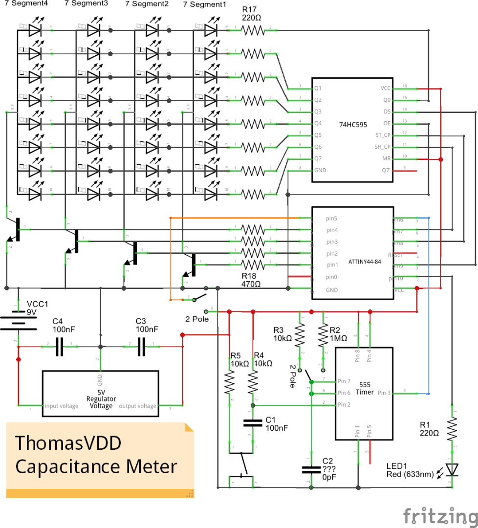
Now it's time to solder everything on a perfboard. Simply replace the capacitor indicated with "???" by some female header pins, so it's easy to insert the capacitors. Making your own PCB is also perfectly possible, I included the file with the schematic in Fritzing. After that, the only thing left to do is measuring some capacitors!
My results were quite accurate and it works great. For even more accuracy, you could use an external crystal instead of the built-in clock of the ATTINY or ATMEGA chip. One more thing would be the use of interrupts to detect the rising and falling edge, but I couldn't get that to work on the ATTINY. If you know how it's done, feel free to leave it in the comments!
To start a measurement, insert the capacitor in the header pins (remember to respect the polarity when measuring electrolytic capacitors), set the measuring range (with the 2-pole switch) and press the pushbutton.
Enjoy your home-made capacitance meter!


