

Introduction: Capturing Motion With an Arduino Accelerometer W/ XBee Comms
***************************************
*** UPDATED 10 JUNE 2014***
As promised, this Instructable has been updated to include a section concerning XBee communication. In addition, a new Instructable will be published soon concerning the development of the rover portion of this project.
Also, the main code that runs on the Arduino has been updated. Please download the new code so you can use the XBee communication.
***************************************
This Instructable is the first part in a two part project that I started this summer. The goal of this project was to create a gesture controlled robot using Arduinos.
The project breaks down into two key phases:
Phase 1: Creation of a gesture control unit capable of send wireless communications to a mobile rover platform. The development of this control unit will be discussed in this Instructable.
Phase 2: Creation of a mobile rover platform capable of receiving wireless commands from a gesture control unit. An Instructable detailing the development of this phase will be published soon.
The following is a brief description of the requirements for the gesture control unit:
Firstly, the Arduino powered unit must be capable of detecting motion. Then, the unit must correlate the motion to a set of predetermined motions. Next, the unit should be able to provide visual feedback and instructions to the users via an LCD display. Lastly, the unit must be able to transmit the signal via wireless communications.
Step 1: Acquiring the Necessary Parts
The following is a list of the parts used in the gesture capture unit. In addition, the websites and relative price of each component are included.
Make Getting Started with Arduino Kit, Radioshack, $65
-This kit includes an Arduino Uno R3, USB programming cable, medium sized breadboard, mounting surface, and assorted wires.
ADXL335 Accelerometer, Adafruit Industries, $15
-This is the primary sensor used to sense motion. It only detects accelerations of approximately 3g's. However, this should be enough for the scope of this project.
RGB LCD Shield 16x2, Adafruit Industries, $25
-This is the primary display and feedback system for the user. This LCD will be used to provide instruction and data to the user from the rover and the accelerometer. In addition, the LCD also tells the user what command their motion has generated. There are cheaper LCD displays available. This shield was chosen for easy stacking and compatibility.
XBee Shield for Arduino, RoboShop.com, $6
-This shield used to connect a XBee wireless transmitter/receiver to an Arduino. This connection can be done without the shield using TX/RX pins on the Arduino. The shield was bought to save space and stack shields.
XBee 1mW Wire Antenna - Series 1 (802.15.4), SparkFun, $23
-The XBee was chosen for its acceptable range and ease of compatibility with the Arduino platform. There are probably cheaper ways of establishing a wireless communication link.
9V Battery Holder with Switch, Adafruit Industries, $4
-This battery holder was bought simply to provide an on/off switch for the control unit. An on/off switch can be accomplished many other ways.
Tools
-Soldering Iron
-Solder, desoldering braid
-Screwdriver
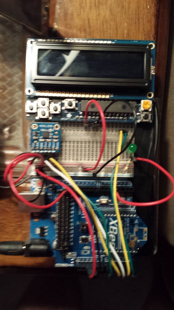
Step 2: Construction and Connections
The first step towards construction of the control unit is to build the shields. This is done by simply soldering all of the necessary pins into the board. Adafruit Industries provides excellent instructions on how to properly construct these shields. These guides also provide nice wiring guides and test code. However, I will go into the wiring and code in depth here as well. I've included the links to the setup guides below:
ADXL 335: https://learn.adafruit.com/adafruit-analog-acceler...
RGB LCD Shield: https://learn.adafruit.com/rgb-lcd-shield
With the shields and sensor properly constructed, the shields can be wired together with the Arduino Uno. The next step will show the wiring for the ADXL 335.
Step 3: Connecting the ADXL 335
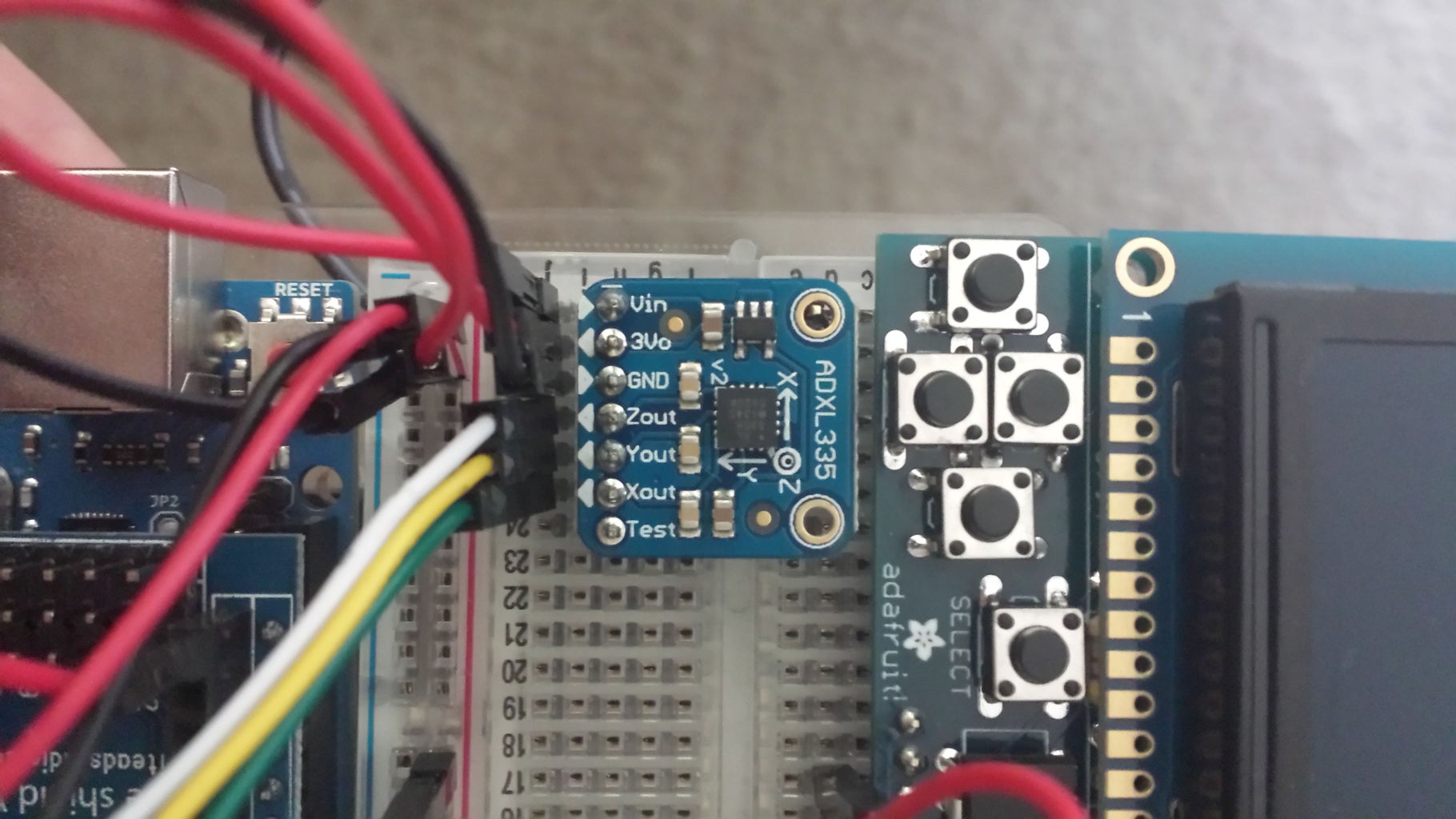

The connection between the ADXL 335 and the Arduino can be accomplished using 6 wires. The first connections are simply the 5V power and GND connections. The next three connections are for the output data from the 3 axis of the accelerometer. Each of these outputs requires its own analog input pin. For my board, I chose pins A0, A1, and A2 for the X, Y, and Z outputs, respectively. The last connection needed is the 3Vo connection. This pin needs to be wired to the AREF pin on the Arduino board. This connection gives the sensor a baseline noise level for the Arduino. Without it, the readings will be quite useless.
Step 4: Connecting the LCD Display
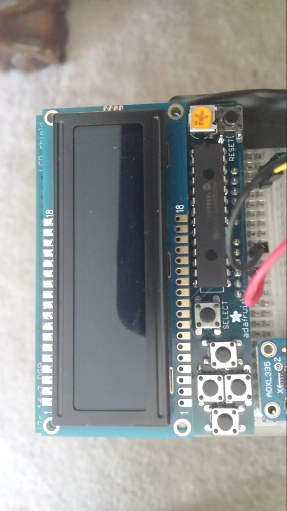

This shield, not stacked (as shown), requires only 5V, GND, and 2 analog pins. This LCD requires the use of the I2C pins on the Arduino, found on A4 and A5. Looking at the shield, moving from the Reset button to the left, bottom row of pins, the 1st pin needs to be connected to A5 and the 2nd pin needs to be connected to pin A4. The GND pin is the 8th pin from the right and the 5V pin is the 10th pin from the right. The connections can be seen above.
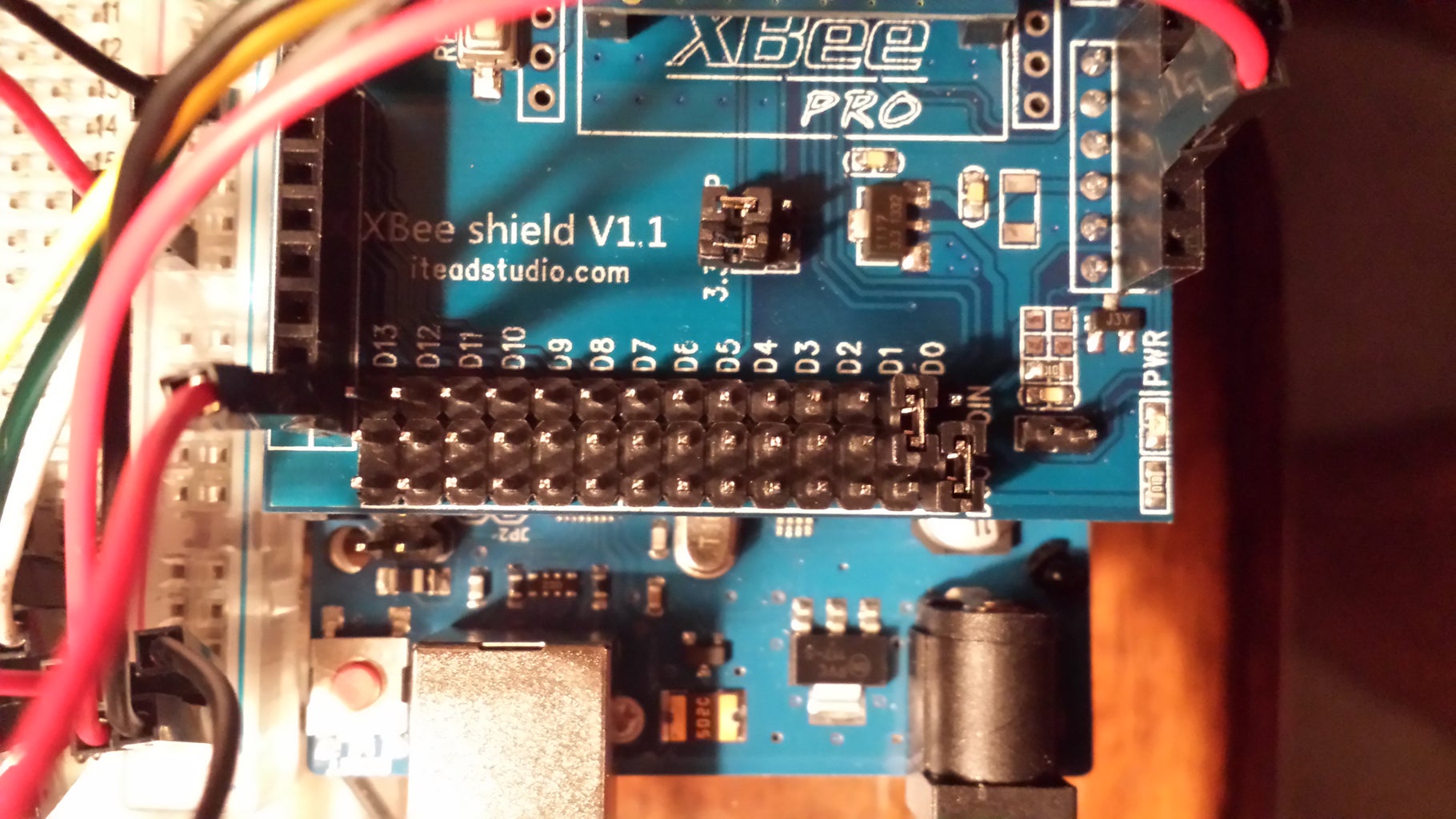
Step 5: Connecting the XBee

Connecting the XBee is as simple as could be. Simply place the XBee unit into the appropriate slots on the shield (See image for correct orientation). Then, place the shield on the Arduino, again, see image for proper orientation. Lastly, reconnect the the wires for the accelerometer and the LCD into the same place they were on the Arduino.
Step 6: Some Notes on the XBee

Using the XBee can be tricky and confusing if you don't understand what/how the XBee unit communicates both with the Arduino and with other XBees. This section will try and explain as best I can how the to program the Arduino with the XBee attached as well as use the XBee to transmit and receive information.
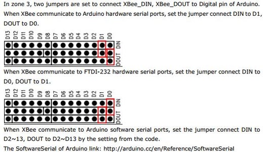
To begin, it should be noted the the XBee is a serial communication device. Since that is the case, the XBee must use the Tx and Rx pins (D0 and D1). This presents a problem. The USB connection for the computer also uses these pins to talk to the Arduino. Because this is the case, you cannot use the XBee and the USB at the same time. To fix this, you must use jumpers provided with the XBee shield to switch between wireless XBee communication and USB communication.
To program the Arduino, the shield must be in USB communication mode. This means the jumpers must be placed in the second position seen in the pin diagram and again in the first image of the shield.
To use the wireless XBee communication, the shield must be in XBee mode. This means the jumpers must be placed in the first position seen in the pin diagram and again in the second image of the shield.
This was one of the most difficult parts of the project. Since it was so difficult, I've included some debugging code in the section so you can test your XBee connections before moving forward. Inside this zip file there are 3 programs. One is for the receiving board, one is for the transmitting board, and the other is a setup script that can be used to customize the XBee hardware using the X-CTU terminal. The transmit code tells the receiver to turn on and off an LED based on a received character.To test the XBee comms, load one Arduino with the transmit code and another with the receive code. Make all of the appropriate connections, and watch the LED turn on and off.
One more note on the XBee, timing is EVERYTHING. Make sure that there are no unnecessary delays or hiccups in your code to slow things down. Also, it is of the utmost importance to clear the serial buffer (using Serial.flush() ) after each reading cycle. If you don't, transmitted data will be backlogged in the serial buffer and the rover will act erratically. Clearing the serial buffer after each iteration ensures only the newest command is read.

Step 7: Writing the Code

In these next sections, the code used to employ the control unit will be discussed. These following sections will break down the code as it pertains to the different key sections of the code. Namely, the sections to be discussed are: Libraries and global variables, setup routine, button detection, and LCD/motion detection routine.
Step 8: Libraries and Global Variables
This step will discuss the libraries and global variables needed to implement the motion detection routine. First, let's discuss the necessary libraries.
#include
#include <Adafruit_MCP23017.h>
#include
The Wire.h library comes with the Arduino IDE and does not need to be downloaded. This library allows the Arduino to access the analog inputs needed to read the accelerometer. The other two libraries are there to provide the functions needed to use the Adafruit RGB LCD. These libraries can be downloaded from the Adafruit github repository. In the links provided in earlier steps, the links to the download files can be found. To link the the new libraries to the Arduino IDE, simply extract the .zip file into the "libraries" (not lib) folder under the Arduino program file. You will, however, need to rename the folder because the name it is download as is an invalid name. Simply remove the "-" and the "master" in the name. You will need to restart the IDE to complete the link.
Next, we will discuss the global variables and objects declared to implement the code.
Adafruit_RGBLCDShield lcd = Adafruit_RGBLCDShield(); //define the LCD object as lcd
#define GREEN 0x2 //define the color green for the lcd
The above creates an object called lcd. This object will be used to call specific functions concerning the LCD device. In addition, the definition of GREEN in this case is a hex number used to tell the LCD what color to display the next in. This can be changed by using different hex numbers.
//Declare input pins
const int xInput = A0; const int yInput = A1; const int zInput = A2; int idleX = 0;
The above declares the analog input pins for the accelerometer.
int idleY = 0; int idleZ = 0; int idlemaxX = 0; int idlemaxY = 0;
int idlemaxZ = 0; int idleminX = 0; int idleminY = 0; int idleminZ = 0;
The above initializes the idle variables for the accelerometer. These must be defined as global variables because they are used in both the setup and loop routines. Later, one will see that the idle state is redefined each time the controller is turned on. This prevents errors should the environment conditions change the idle state values.
// Take multiple samples to reduce noise
const int sampleSize = 10;
int dir = 0;
Sample size is declared to reduce noise in the accelerometer measurements. Each time the values are read, 10 samples are taken and then averaged. The variable dir is used to communicate what button on the LCD has been pressed. This tells the LCD what information to display.
Step 9: Setup Routine


This section will discuss the setup routine used in this control unit.
analogReference(EXTERNAL);
The first step in the setup routine is set the analog reference voltage. This step helps to give a baseline for the amount of noise in the sensor readings. Without it, the analog pins wouldn't read any change in reading.
Next, the LCD needs to be set up and a welcome message displayed.
lcd.begin(16, 2);
lcd.print("Welcome to the ");
lcd.setCursor(0,1);
lcd.print("HCRP");
lcd.setBacklight(GREEN);
delay(3000);
The command lcd.begin(16,2) is used to initialize the LCD and give the size of the LCD 16 columns with 2 rows. Next, the command lcd.print() is used to write messages to the LCD. lcd.setCursor(n,m) is used to st the start point for the message. The first number is the column and the second is the row. Counting starts from 0. lcd.setBacklight() sets the background color for the LCD.
Next, the setup routine enters into the calibration phase of the code. Here, the idle state of the controlled is initialized. The idle state is defined as laying flat. This is needed because motion is defined by deviations from the idle state. The default state is idle.
lcd.clear();
lcd.setCursor(0,0); lcd.print("Calibrating ");
lcd.setCursor(0,1); lcd.print("Lay flat");
delay(5000);
idleX = ReadAxis(xInput); idleY = ReadAxis(yInput); idleZ = ReadAxis(zInput);
idlemaxX = idleX+15; idlemaxY = idleY+15; idlemaxZ = idleZ+15;
idleminX = idleX-15; idleminY = idleY-15; idleminZ = idleZ-15;
lcd.clear();
lcd.setCursor(0,0); lcd.print("All done! ");
lcd.setCursor(0,1); lcd.print("Begin Control");
delay(3000);
The command lcd.clear() clears the LCD of any previous writing. Next, the code tells the user that the code is about to enter the calibration phase and that the controller should be flat. The code then gives the user 5 seconds to get the controller into position. After the controller is in the correct position, the code reads the accelerometer and sets the idle state. It also sets an interval for the idle state. The default is (+/-) 15. This is set to account for noise in the readings. Given the circumstances, this value may need to be adjusted. In order to detect motion, the accelerometer values will have to exceed the max or min value for the idle state. Lastly, the code tells the user that the calibration is finished and control of the rover is about to begin.
Step 10: Button Detection

This next step describes the different actions to be taken by Arduino given different button presses on the LCD.
if (buttons) {
lcd.clear();
lcd.setCursor(0,0);
if (buttons & BUTTON_UP) {
lcd.print("Move "); dir = 0;
}
if (buttons & BUTTON_DOWN) {
lcd.print("Z accel "); lcd.setCursor(0, 1);
lcd.print(zRaw); dir = 1;
}
if (buttons & BUTTON_LEFT) {
lcd.print("Y accel "); lcd.setCursor(0, 1);
lcd.print(yRaw); dir = 2;
}
if (buttons & BUTTON_RIGHT) {
lcd.print("X accel "); lcd.setCursor(0, 1);
lcd.print(xRaw); dir = 3;
}
If the UP button on the LCD is pressed, then the Movement detected by the control unit is printed to the screen. This is the default display of the LCD. The variable dir global variable used to define the button that was pressed. It is used later in a switch/case statement to determine what information to continuously display. If the DOWN button is pressed, the raw Z acceleration data is shown. If the RIGHT button is pressed, the raw X acceleration data is shown. And if the LEFT button is pressed, the raw Y acceleration is displayed.
Step 11: Motion Detection

This step describes how the controller decides what kind of motion is happening. Through testing, is was determined that, as referenced from the idle state, this is the pattern that the motion of the controller follows. (G=greater, L=less, S=same)
Ideal: 510, 497, 627
Right 611, 492, 521.....G,S,L
Left 408, 496, 530.....L,S,L
Forward 512, 598, 526.....S,G,L
Reverse 514, 395, 536.....S,L,L
What this is saying is that, for example, in order for there to be motion to the right, the X reading must be greater than idle, the Y reading must be about the same, and the Z reading needs to be less than idle. The same kind of logic follows for the other kinds of motion. In the following code, the switch/case statement uses simple logic to determine the motion. The default case is declare an "error" and not send a motion if for some reason the accelerometer is not detected or lost.
case 0:
lcd.clear(); lcd.setCursor(0,0);
lcd.print("Move"); lcd.setCursor(0, 1);
if (xRaw > idleX && yRaw > idleminY && yRaw < idlemaxY && zRaw < idleZ){
lcd.print("Right");
}
else if (xRaw < idleX && yRaw > idleminY && yRaw < idlemaxY && zRaw < idleZ){
lcd.print("Left");
}
else if (xRaw > idleminX && xRaw < idlemaxX && yRaw > idleY && zRaw < idleZ){
lcd.print("Forward");
}
else if (xRaw > idleminX && xRaw < idlemaxX && yRaw < idleY && zRaw < idleZ){
lcd.print("Reverse");
}
else {
lcd.print("Idle");
}
Step 12: Wrapping Up and Future Work
In conclusion, it is my hope that this Instructable has given some insight into how to setup and use an accelerometer to detect different kinds of motion. In this Instructable, the process to setup and use various sensors and displays such as accelerometers and LCD were discussed. Lastly, this Instructable walked you through how to write use provided code to map motion to accelerometer measurements.
Also, a follow on Instructable will be written to discuss how to build a rover capable of using the motion of this device to move around in an environment.
Attachments

Participated in the
Sensors Contest

Participated in the
Battery Powered Contest


