

Introduction: Car Ramps


Presented with the need to work under my car (one of my least favourite jobs such that i try and avoid it...) the problem arose as to how to get it high enough that i could get under there and stay alive while wielding the "instruments"
When it became obvious that Jacking it up on blocks was not going to easily provide the kind of clearance i needed
i took a wander down to the local auto store to get some of those "ramps" that you see... on arrival i nearly fainted at the price for hopefully a "one off job".. so it was back home to figure another method...
Looking around my wood store i came up with the Mk1 Wooden version:-)
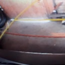
(Image 1 - i didn't think to take and "instructable photo" of the finish ramps, but did manage to capture this form the photos i took of what i was doing...:-) )
Step 1: What I Used;
- Power drill
- 32 mm spade bit
- 12 mm spade bit
- Spade bit extension
- Tape
- Marking pen
- Combo square
- Socket set
- Hammer
- At least a couple of 3500-4000 mm lengths of 100 x 100 timber (how much will depend on your measuring in the next step)
- 4x Coach bolts ( M12 x 250)
- 4x M12 flat washers
- 4x Coach screws (M10 x 100)
- 12 mm Rebar x 1200 mm (add cutting tolerance depending on your blade width)
Step 2: Measure and Cut
First i laid the tape up against my tire and worked out how much tire touches the road, how high i wanted to go.. and how long the top level to be. ( guess its going to be different for each car?)
I then made my base layer length approx 200 mm longer then the top layer ( the mark 11 version would be 300 mm)
so by calculations i cut;
- Base: 4 x 800 mm(I used my chainsaw made allowance for the blade width while cutting)
- Layer two: 4 x 300 mm
- Layer two: 6 x 200 mm
( if i was to go to Mk 11, id make the top level 100 - 150 mm longer, and the base level and extra 200 - 300 mm longer to allow for the approach angles)
Step 3: Construction - Base Level

- I took the 4 x 800 pieces (which form the base layer) and stacked them vertically in pairs, lined up the edges and placed on blocks off the ground
- Using the M12 spade bit and extension, then drilled two holes through both, at either end of the lengths (Diagram 1.)
- Pushed the M12 coach bolts through the holes, with a final tap on the head to seat the square that stops the bolt turning when its tightened.
- Washers on, bolts on - tightened up
- Repeat for the second pair
Step 4: Level Two.1


- Marked the beginning of level two across the base level
- Took the 300 mm blocks and divide then in to 2 pairs
- Then placed the first pair in the same direction as the base level pair against the marked line. (Diagram 2)
- Using the 32 mm spade bit drill, bored a counter sink hole down 50 mm into the top to of each block
- Then followed down the hole centre with the M10 spade bit drill through the block in to the base blocks
- Screwed the coach screws down into the counter sinks. (Diagram 4)
Step 5: Level 2.2 and 3


- Then took one of the 200 mm blocks and place it across at right angles to the first two blocks - on the other side of the marked line seen in diagram 4 (Diagram 5)
- Took a second 200 mm block and lay it parallel to the first so its edge is flush with the ends of the base layer
- Took the third 200 mm block and stacked it on top of the second so that it forms a third layer. This level will be the wheel stop.
- Using the 12 mm spade bit with extension, i drilled two vertical holes on the end level from the top through the second layer and in to the base.
- Using the hammer, knocked the two of the 12 mm lengths of rebar down through each hole to anchor the end blocks in place(Diagram 6)
Step 6: Finish

- Then flip the entire lot on its side and then i marked the black line at approx 60 degrees and cut to the line with the saw. (Diagram 7)
- It was here i realized i could have done with more length on the base layer: to ease the approach:-)
- I figured it was a bit steep, so i then cut the red line to shallow it up a bit.
The climb was a bit steep and abrupt with a little wheel spin but it worked:-)
I took two of the triangular off cuts from the last cut and used them as chocks behind the back wheels... of course after the work was done i had totally forgotten about them - that is when i found out how good they where- the car wouldnt budge when i tried to drive off;-)


