

Introduction: Cheap DIY DDS Function/Signal Generator


These DDS Signal Generator module boards can be had for as little as $15 if you look around. They will generate Sine, Square, Triangle, Sawtooth (and reverse) waveforms (and a few others) fairly accurately. These also have touch controls, amplitude and offset adjustments. Add in a case for about $10 and you're laughing.
The module board run's off low voltage (7-9V), so they're safe for novices. It will actually run off 12V as well (as I do with mine), so you can use a wall wart power supply. Although, you could put AC in there if you so desire. The module only uses a small amount of current so even a small switch mode PS would do. With a few extra components you've got a fully functioning bench style signal generator. Best of all, the module is pre-build so they're tested and guaranteed to work (you can get unassembled kits as well).
Most of the work in this project is modifying the board so that it can be mounted in a bench style enclosure. You can buy these pre-built in a small box. I wanted mine for the work bench.
Step 1: What You'll Need to Buy


A DDS Function Generator module board - these can be found on Ebay, aliexpress etc for about $15-20, prebuilt , tested and functioning.
Male header connector strips - again ebay. Buy a long strip and you can cut them down for whatever length you need.
Header cables - either build them yourself if you have the individual pins and casings or you can get them from Jaycar. They were out of the male/females at the time, so I bought male/male and changed one side over to female.
Single core shielded cable - similar stuff you use for low power audio signals
12/24V switch - I used a 24V LED switch. It's a little less bright running it off 12V, but any switch will do.
Male DC panel mount connector and female plug socket - I had a few different styles so I was just using up the old style I had. You can get them in a plastic single drill hole style which are easier to mount.
Couple of nuts/washers for the BNC connectors or buy new BNC panel connectors as the kit doesn't have them. I took a couple off a foot switch I had.
4 small M3 hex male/female stand offs for the LCD (to replace the longer ones supplied in the original kit module)
I also changed out the control knobs from the red ones supplied to some more generic white knobs.
The silver knobs/top hat style buttons I also had laying around from another project, but they're cheap to buy a pack of 50 mixed colours.
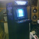
Some sort of instrument case. The one pictured you can buy them for about $12 off ebay, cheaper if you buy a couple together (if you have other projects - I use them for power supplies as well).
Step 2: Modify DDS Module

Before doing anything to the board - VERIFY IT WORKS FIRST! Plug the board into 9-12V power supply and verify everything's running how it should before you start modifying. Nothing worse then spending all that time changing the board on something that didn't work in the first place.
The first thing to do is to remove components that will be going on the front panel (unless you bought the un-assembled kit - then you can leave those components off). BE CAREFUL as excessive heat can remove pads and tracks. Best off adding a little solder and then remove all with a solder sucker.
Remove:
- The two output BNC connectors,
- The two pots
- Five push button switches
- The LCD board from the header as one unit.
Now solder in headers in place of the BNC connecters, the pots (you can use a five way header with pins 2 & 4 removed for spacing).
Solder in 6 single headers for the switches. Even through there's four pads, two sets are connected per side so either pin will do. You can go off the photo to see which pads are what, however I strongly recommend buzzing the board out yourself in-case they change the board layout. You'll find one side of the switches all connect to each other (the common). In my case, I've used the red wire as my common (looking back, I probably should have used black). All the rest are the other side of the switch and either side of the pad works as a connection point.
Again, I've used single wires in-case one switch is doing the wrong function, they're easily swapped around ( I think that's why I didn't use black, the wire was too short).
A NOTE ABOUT THE LCD CONNECTING HEADER:
I found that putting the header through the vero board doesn't leave a lot of grip for the connectors to connect with. If you can find extra long header pins that would be the go, or a long male/female header extension.
Step 3: Modify Display Board and Front Panel Switches


The display and control panel looks more intimidating than it actually is. Basically, the large vero board on the back holds both boards together (the existing LCD screen and new push button board).
For the LCD display, the pins just push straight through the back of the vero board and will attach to the main board via a male/female header cable. Just remember to cut the tracks just under connectors. Also see the notes earlier on pin lengths.
For the switch board, space the switches out how you like them. Basically, one side will be a common (so you can connect them all to one rail) and then I've poked individual header pins through the board to attach the wires (for the main board). I've also attached the male end of the header wire to the board (as they kept falling off). However, you can use the longer headers if you can find them. Again, just make sure you cut unnecessary tracks on both vero boards.
Ergonomically, it makes more sense to have the vero running down the board (long ways) for a common between the switches. However, you also waste a lot off one side of the vero board. So it's easier to just cut a small length off the end of a full board and deal with it that way.
A Couple of Notes:
I put the switches one row too high and should have been lower. I didn't have the switch caps at the time and the side of the cap got in the way of the LCD display standoff's - hence why you see the side of the cap cut off on the two end switches. I assumed that the cap wouldn't be much bigger than the switch. We all know what happens when we assume.
Why did I solder the switches on the copper side of the vero board? Because the interconnecting header pins needed to be spaced similarly to the LCD headers. That way the switch board didn't sit any further forward behind the front panel. It just fits and doesn't cause any ill effects with the switches not working correctly.
I had to enlarge some of the switch holes on the front panel, as the switches didn't sit entirely square in the vero board. So some switches were offset slightly.
Yeah, I know one of the corners of the vero board broke when I drilled it! Again, the vero probably could have been one hole higher.
Step 4: Putting It All Together


Okay, so the first thing is to drill the front panel out for the LCD screen, power button, switches, pots and output BNC's. Space it how you want, I wanted the screen in the centre and 2 BNCs under the controls so any cables didn't get in the way. Power switches I generally like on the left.
I've used some rub on lettering for the front control panel. Then gave it a light spray of clear over the top. Unfortunately, the clear sometimes makes the letters run or can crack/craze them. Once you've put your letters on and it's dried, mount the components to the front panel. The LCD screen assembly is mounted with a couple of M3 stand offs, using the original holes of the board. It attaches to the vero board via M3 screw and nut
Next, drill a hole for the DC connector in the back and mount the DC panel socket.
Once all of these things have been mounted, it's time to interconnect the modules and boards. I've allowed a little extra in the cable lengths so that with the front and back panels out, they can sit lay down.
For the pot leads, I used single headers as I wasn't sure whether the controls would function in the right direction so it's easy to swap when they're single.
I've used a DC female connector to connect power to the board incase the module ever goes "bung". Then it's relatively easy to replace the whole board. As was the case with the first board - I'd accidentally connected a couple of the display leads wrong way around and buggered the board - Oops!
See the note in step 2 regarding the header pins!
Now hook up all your leads, add some power and see if it's functioning correctly. Fingers crossed everything's functioning how it should.
Hope that you found this instructable useful and it at least gave you some ideas for your own version.

Participated in the
Build a Tool Contest


