

Introduction: Circuit Testing

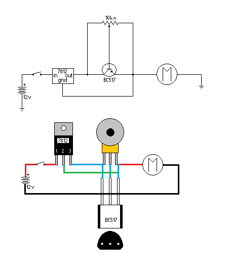


I spend a little time in the Q&A here at Instructables answering questions and sometimes building and testing a circuit like this one to control a PC cooling fan speed. This member at Instructables wanted to control the speed and slow the fan down as much as possible, this circuit doesn’t change the voltage it changes the current so there is little chance of burning out the motor. Since I have a mass of components to work with and time on my hands I can build and test a circuit without spending much more than my time.
One question being asked by members indirectly trying to answer a question in Q&A is, “How did you test the circuit?”
The answer you get from your meter or oscilloscope may not be what you get from your circuit there is a thing called LOADING EFFECT. Sometimes your meter lies to you.
This Instructable is about the proper testing of a circuit or prototype in order to answer the question asked so often in Q&A, “Why doesn’t my circuit work?”
Step 1: Overloading


Many of you may be familiar with this circuit it is a 555 timer used to make a Theremin, you may call it an Optical Theremin, or a Pocket Theremin. (A light controlled sound synthesizer.) They work well indoors, with a single light source that can be easy to control the amount of light received by the photo resistors.
However if you take this circuit outside in the sun all you get is a high pitch whine out of it unless you completely cover the photo resistors. The circuit doesn’t work the way it was designed because it is overloaded by light, the sun bounces off everything around you to your hand to the photo resistors.
This is called overloading and it is one kind of loading effect you need to avoid when testing a circuit or the circuit will not respond the way it is designed.
Step 2: Under Loading a Meter


In Q&A many of the members wonder why there circuit gives them what it should be giving them when they test the circuit with a meter, however when they hook up their circuit to a load it doesn’t work, they may be under loading the circuit they are testing. Under the same test conditions I tested a solar cell.
In the first pic I connected a meter to a solar cell and got a voltage of 4.34 volts.
Next I connected an appropriate load in this case a 100Ω resistor to the solar cell as in pic two I play a lot with these solar cells from garden lights so I know what size of a resistor to simulate the circuit.
Then when I checked the voltage I get 3.34 volts as in pic three a one volt difference, making the first reading almost 25% out.
This loading effect is called under loading the current coming out of the solar cell is misinterpreted as voltage by the meter, unlike the complete circuit with the 100Ω resistor bypassing the current and showing the voltage.
If I wanted to make a 12 volt solar array with these solar cells I might use three solar cells if I were to use the reading 4.34 volts in the first pic and only get a 9 volt array when hooked to a circuit. However using the loaded circuit readout of 3.34 volts to make a 12 volt solar array I would use 4 of these solar cells and my circuit would work.
Step 3: Under Loading an Oscilloscope

The same thing happens when you under load an oscilloscope the current coming out of the circuit is misinterpreted as voltage by the oscilloscope. Sometimes loading effects can be useful, I do a lot of reverse engineering this is a skill you need if you want to make a clone of a circuit or to repair circuits you cannot get the schematics for.
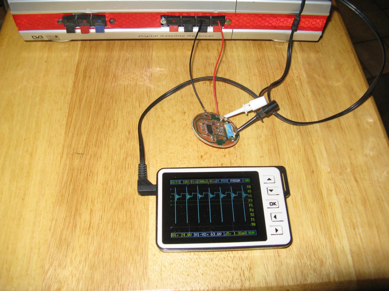
This is the circuit from a Piezo buzzer that had the driver circuit in the buzzer. I accidently damaged the buzzer while disassembling the device it came from so I decided to reverse engineer the buzzer.
First I traced and mapped out the circuit with the values of the components I could tell with the help of my SMD code book. This didn’t work for all the components like the ceramic capacitors and the inductor coil since they had no markings.
Then I connected the circuit to my power supply and the output of the circuit to my oscilloscope without a load as in the next pic. Notice the distorted output signal and I am sure a 5 volt circuit without a step up transformer won’t produce a 63 volt peak to peak output. This is the loading effect of the current being confused by the oscilloscope as voltage.
Step 4: Everything Is a Resistor

Everything in a circuit for testing purposes is a resistor; a capacitor is a storage device and an insulator with DC current and a resistor with a signal. An inductor is a dead short with DC current and a resistor with a signal. You can do this for every component and circuit while testing.
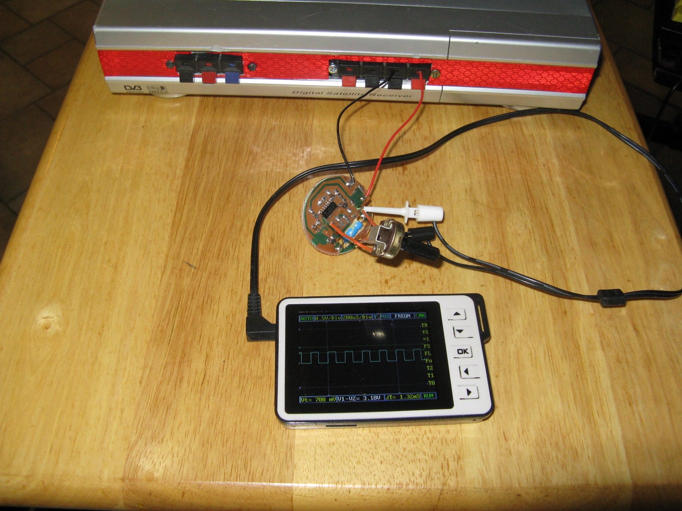
In the first pic I replaced the Piezo Buzzer with a 10 kΩ resistor, this smoothed out the signal a little. If you know the load of the circuit you are testing you can just replace the component with a resistor and get the output you want, however that is only if you know the value of the component.
In the next pic I replaced the 10 KΩ resistor with a 50 KΩ pot and adjusted the pot until I got the strongest and clearest signal I could get then I disconnected the pot and checked the resistance.
The Piezo Buzzer’s specks are3 volts, 3 KHz, and 25 KΩ.
Armed with 3 volts, 3 KHz, and 25 KΩ I can find the nF for the Piezo Buzzer and then I can calculate the Inductor and capacitors using the formulas f = 1/2πCR, XL = 2πfL, and Xc = 1/2πfC.
Step 5: Why Isn’t My Circuit Working?


Are you testing it the right way?

Participated in the
Kit Contest

Participated in the
Epilog Challenge V

Participated in the
Battery Powered Contest


