

Introduction: Connecting RF Transmitter and Receiver to Arduino


The RF(Radio Frequency) Module operates at radio frequency, The corresponding range varries between 30khz & 300Ghz, in the RF system, The digital data is represnted as variations in the amplitude of carrier wave. This kind of modulation is known as Amplitude shifting key (ASK). The signals transmitted through RF can travel through larger distances making it suitable for long range applications. RF transmission is more strong and reliable.. RF communication uses a specific frequency range.. This RF module comprises of an RF Transmitter and an RF Receiver. The transmitter/receiver (Tx/Rx) pair operates at a frequency of 434 MHz. An RF transmitter receives serial data and transmits it wirelessly through RF through its antenna connected at pin4. The transmission occurs at the rate of 1Kbps - 10Kbps.The transmitted data is received by an RF receiver operating at the same frequency as that of the transmitter.
Features of RF Module:
1.Receiverfrequency 433MHz.
2.Receivertypical frequency 105Dbm.
3.Receiver supply current 3.5mA.
4.Low power consumption.
5.Receiver operating voltage 5v.
6.Transmitter frequency range 433.92MHz.
7.Transmitter supply voltage 3v~6v.
8.Transmitter output power 4v~12v
In this Post you guys will know about how to transmit the data from one place to another place wirelessly for achieving this here we used an Rf Transmitter and Receiver module. Rf transmitter will send some characters to Receiver section, Based on the character received, Encoded Message will be displayed on the LCD display in the receiver Section. The Rf transmitter and Reciever will be connected to an arduino board on tx and rx end, befor going to start the connections we need some hardware components that are listed below.
Step 1: Components Required
Hardware components
1. RF Transmitter and Receiver
2.Arduino uno (2 boards).
3.LCD 16*2 display
4.jumper wires.
5. Breadboard (optional)
6.Soldering gun
Software Required
1. Arduino IDE
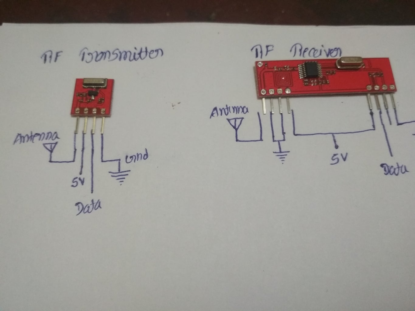
Step 2: Connecting RF Transmitter and Receiver to Arduino


Connection Of RF Tx & Rx to Arduino
Make the connections as per the circuit diagram, for implementing an Rf Tx & Rx we need two arduino boards, one for Transmitter and another one for Receiver. Once you connected everything as per the circuit diagram. The module works fine
Step 3: Code
Code
Before going to upload the code to your Arduino First download the library from here http://www.airspayce.com/mikem/arduino/VirtualWir...
Transmitter code
#include // include virtual wire library file here
char *controller;
voidsetup()
{
vw_set_ptt_inverted(true);
vw_set_tx_pin(12);
vw_setup(4000);. // speed of data transfer Kbps
}
void loop()
{
controllerer="9" ;
vw_send((uint8_t *)controller, strlen(controller));
vw_wait_tx();
// Wait until the whole message is gone
delay(1000);
controller="8" ;
vw_send((uint8_t *)controller, strlen(controller));
vw_wait_tx();
// Wait until the whole message is gone
delay(1000);
}
Receiver Code
#include // include LiquidCrystal library file here
#include // include virtual wire library file here
LiquidCrystal lcd(7, 6, 5, 4, 3, 2);
charcad[100];
int pos = 0;
voidsetup()
{
lcd.begin(16, 2);
vw_set_ptt_inverted(true);
// Required for DR3100
vw_set_rx_pin(11);
vw_setup(4000); // Bits per sec
vw_rx_start(); // Start the receiver PLL running
}
voidloop()
{
uint8_t buf[VW_MAX_MESSAGE_LEN];
uint8_t buflen = VW_MAX_MESSAGE_LEN;
if (vw_get_message(buf, &buflen))
// Non-blocking
{
if(buf[0] == '9')
{
lcd.clear();
lcd.setCursor (0, 0);
lcd.print("Hello Techies");
}
if(buf[0] == '8')
{
lcd.clear();
lcd.setCursor (0, 0);
lcd.print("Welcome to ");
lcd.setCursor (0, 1);
lcd.print("Pro-Tech Channel");
}
}
Step 4: Result


Step 5: Follow Us On
Click on the link below and follow the blog for more updates
https://protechel.wordpress.com
Thank you


