

Introduction: Control CoTech Remote Switch With Arduino (433Mhz)

A short while ago I bought 3 Co/Tech 51058x10 remote switches and a 50027 remote from Clas Ohlson in Norway. They use the AM 433mhz band to communicate. I wanted to control them with an Arduino, and after googling and reading a long time, I couldn't find that anyone have connected that specific brand to an Arduino before me.
You need:
Co/Tech remote switches:
http://www.clasohlson.com/no/Cotech-Smart-Home,-fj...
http://www.clasohlson.com/uk/Remote-Switch-Set-3-P...
433Mhz reciever and transmitter:
http://www.ebay.com/itm/400492821250?_trksid=p2057...
Ardunino board (I'v used the Nano)
http://www.ebay.com/itm/Mini-USB-Nano-V3-0-ATmega3...
Step 1: Setup and Wiring


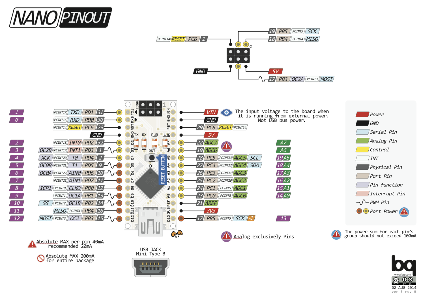

The receiver im using has 4 pins and the transmitter has 3. Connect them to the arduino as in the pictures. Each with 5v, ground and a data pin.
It is important that the datapin of the receiver is connected to pin D2 or D3 of the Arduino because it has to be connected to a interrupt-pin. The transmitter can be connected to another digital pin if you want, but you then have to alter the code of course.
Step 2: Research

Since none had connected to this Co/tech model before me I did not know how it communicated. By opening the remote gave me the model nr. 50027.01B FLF-130105
A big help: http://forum.arduino.cc/index.php?topic=201771.15... (Special to wex_storm and windkh)
A good library makes every makers life easier. The one that worked the best with my unit was RCSwitch by sui77. http://forum.arduino.cc/index.php?topic=201771.15... (Arduino lib to operate 433/315Mhz devices like power outlet sockets.)
I also used some code from an example in this lib: http://forum.arduino.cc/index.php?topic=201771.15...
Step 3: The Coding
To control the switch we need it to think that the remote is beeing used by coping its remotes codes and transmitting them on demand from the arduino.
The first thing you do is to start the example in the RCSwitch lib "ReceiveDemo_Advanced.ino" and upload it to the arduino. Watch out for the confusing pin naming as the library uses the nr for the interrupt-pin and not the digital pin nr.
mySwitch.enableReceive(0); // Receiver on "interrupt 0" => that is digital pin 2 and "interrupt 1" => D3.
Now start the serial window and press one of the buttons on the Co/Tech remote.
You should get something like this:
Decimal: 11001351 (24Bit) Binary: 101001111101111000000111 Tri-State: not applicable PulseLength: 517 microseconds Protocol: 5
Raw data: 7200,1004,528,504,1048,980,336,1176,356,1176,352,1180,1108,412,356,1172,364,1168,356,1160,1176,1124,412,336,1180,1116,440,328,1188,340,1228,1060,416,1160,380,1160,1108,464,1068,436,328,1232,1060,412,1116,440,1088,428,3024,
This means that the Arduino is reading the reciever. The mots interesting thing is the binary code. This remote sends a 24 bit code. This may differ from different units.
1010 0111110111100000 0111
^ ^ ^ ^ ------------------------ ^ ^ ^ ^
The first 4 digit is the "name" of the remote. The last 4 is the the name of the button that is pushed. The 16 nr in between is a random code.
If you press the same button again it will show the same four nr (1010) in the start and the same four nr (0111) in the end. The 16 nr i between will probably change. Each button on the remote can send 4 different 24bit binary codes.
To save time and make it easier to collect all the "secret codes". I'v used the code from the flamingoreader.ino example in the FlamingoSwitch lib and change it to work with RCSwitch. It makes it alot easier to scan for all the binary codes from the remote control, and then you can copy and paste them to a text file for storage. (Download the the RecieverDemo_Scan.ino file and add it to the RCSwitch example folder)
Upload the RecieverDemo_Scan.ino file to the Ardunino and press one of the buttons on the remote until you see "Scan complete".
Counter: 0 Code: 11446759 Code: 0xAEA9E7 Bin: 101011101010100111100111
Counter: 1 Code: 11001351 Code: 0xA7DE07 Bin: 101001111101111000000111
Counter: 2 Code: 11092535 Code: 0xA94237 Bin: 101010010100001000110111
Counter: 3 Code: 11340023 Code: 0xAD08F7 Bin: 101011010000100011110111
Scan complete.
We now have all the binary codes for this button. Now do the same for all the buttons and save them in a text file for later.
Attachments

Step 4: Controlling the Socket With the Arduino

To pair the remote to the switch press the button on the switch for 3 seconds and it will start blinking. Now press the ON button on the remote that you want to use for controlling the switch. They now should be paired. You probably could pair with the Arduino by making a sketch that does the same.
Now find your recorded binary code from earlyer. Download the code rfTest.ino and edit it to fit your needs. Change the binaries in the code to your specific remote and button.
The RCSwitch said that the remote used a "Protocol: 5", but in testing that failed and protocol 4 worked better.
mySwitch.setProtocol(4);
The pulseLength can be changed. I found that 400 work ok, but you can try tweeking it.
mySwitch.setPulseLength(400);
The switch needs at least two of the four 24 bit binary from each button on the remote to react.
Serial.println("Turn on with Button A"); // testing show that not all the codes are neeeded. But atleast 2 per button
mySwitch.send("101001011011111101000111");
mySwitch.send("101000011111000011000111");
//mySwitch.send("101001001100011010010111");
//mySwitch.send("101000101001101011010111");
Now upload the sketch and it should work.The switch turns off and on again every 5000ms.
PS: I had some problem with the "OFF" codes when powering the arduino with the pc to usb. Connecting the Arduino to a external power source solved the problem. Maybe its the noise from the usb connection thats jamming the transmitter. I don't now yet.
Attachments
Step 5: Thanks for Reading
Hope this guide helped you.
I'm no pro and if there is any mistakes please comment and tell me.
Best regards Øyvind Haga


