

Introduction: Control K'nex With a Mobile Phone


In this instructable, you will learn how to make a K'nex Bobble Car. It is so named because the code you will be using for this project is open source software I developed called "Bobble" which runs on an Arduino board and responds to easy one letter commands to control one motor, one servo, and one analog input from an attached sensor. This instructable can be very easily generalized to other K'nex (and even non-K'nex) projects.
We will be using an Adafruit nRF52832 Bluefruit LE board which combines an Arduino processor and Bluetooth LE (Low Energy) driver. Using a Bluetooth LE connection, you will be controlling the bobble with an Android phone application that was written using App Inventor 2 which is a visual programming tool that makes application development super easy. Although I will provide you a link to directly load the application file on to your Android device, I also encourage you to open the source code for the project under App Inventor 2 so that you can see how the simple application works and modify it as desired. The code was designed to be easily understood and modified.
Step 1: Required Parts for This Project

Besides the K'nex parts shown here, you will also need the following parts:
1 Modified K'nex motor (see link2_thepast's excellent instructable Arduino + K'nex Motor)
1 Half-size solderless breadboard (400 Point)
1 Modified 9g micro servo (instructions in this instructable for adding K'nex parts)
1 Adafruit Feather nRF52 Bluefruit LE - nRF52832
1 L293DNE 4 channel motor driver
1 Silicon NPN Phototransistor
1 10K ohm resistor
1 (optional) 3-pin male to male header [just snap apart a larger header]
1 3x AA Battery Holder (with switch) and 3 AA batteries
NOTE: For the modified K'nex motor, you will only need the two leads connected to the motor. The power and ground leads will be unnecessary for our purposes since we will be using an external battery case.
If you would rather just bypass all of these steps and just purchase an assembled K'nex Bobble Car for $68, just contact me and we can set you up with one today.
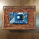
Step 2: Constructing the Bobble


Headers will need to be soldered into the nRF52832 so that it can be mounted on the half breadboard. Also mount the L293DNE motor driver chip as shown on the breadboard. All of the rest of the wiring should be pretty straightforward as shown.
NOTES:
1. The left hand (+) bus rail will be 3V. The right hand (+) bus rail is attached to the Battery and USB outputs and will be between 4.5V and 5V depending on whether you have a 3AA battery pack or USB cable attached for power. The left and right (-) ground bus rails are wired together.
2. The servo will be attached as shown. However, you may want to install a 3-pin male to male header on the lower part of the board and wire the pins to nRF528232 pin 11, Battery/USB power, and ground respectively. In this way, you can just plug the servo directly into the header. The photo of the bobble shows this configuration.
3. The motor connection is where the modified K'nex motor will be attached.
4. The nRF52832 A0 analog input is wired to the NPN phototransistor and pull up resistor. The phototransistor's emitter (usually the long lead) is the one connected to ground.
We are now ready to load the Bobble firmware on the nRF52832.
To save yourself a little time and energy on this and the next step, you can purchase a pre-programmed Adafruit nRF52832 Feather with headers already soldered in for $35. Just contact me and we can set you up with that today.
Step 3: Load Bobble Firmware on the Adafruit NRF52832 Bluefruit LE
1. Follow the directions for setting up Arduino IDE to work with the nRF52832 Bluefruit LE at
https://learn.adafruit.com/bluefruit-nrf52-feather-learning-guide/arduino-bsp-setup
NOTE: The installation process for the board is slooow, it took 1/2 hour to totally load on my PC and much of the time it was unclear that anything was happening. BE PATIENT, it will install.
2. Download the Bobble code at:
https://github.com/reachandteach1/bobble-nrf52/raw/master/ble_bobble52.zip
3. Unzip the file after you download it and remember where you put the unzipped directory ble_bobble52
4. Connect the nRF52832 via USB cable to your PC's USB port
5. Launch Arduino IDE and open ble_bobble52 from wherever you stored it in step 3
6. In the Tools menu, select the board Adafruit Bluefruit nRF8232 Feather
7. No changes to the code should be required, so just Compile and Upload
NOTE: I sometimes have problems with my antivirus checker interfering with the compilation process and causing an error to occur. I find that just putting my PC into Airplane Mode while compiling fixes the problem.
8. If everything works correctly, you will see a blinking blue light on the nRF52832 meaning that it is waiting for something to connect to it. Opening the serial monitor window under the Tools menu will display something like:
Reach and Teach BLE Bobble
---------------------------------------
MOTORENABLE=7
MOTOROUT1=16
MOTOROUT2=15
SERVO=11
ADCIN0=A0
CONGRATULATIONS! You now have a working Bobble and you are now ready to load the RTBLEBobble application on your Android
Step 4: Load the RTBLEBobble Application
Loading the RTBLEBobble application is easy... Simply point your phone's browser to:
https://play.google.com/store/apps/details?id=appinventor.ai_derrick_kikuchi.RTBLEBobble
This will let you install the application from Google Play Store.
So that's all there is to loading the application. However, you can also load the application using App Inventor 2 and that will allow you to see the source code for the application and even modify it.
Alternatively, to view and download the application using App Inventor 2:
1. Go to the App Inventor website at MIT:
http://ai2.appinventor.mit.edu
and sign in (you will need a Google account to do this)
2. Under the Projects menu, select "Import project (.aia) from a repository..." which will bring up a popup window called "Create a Project from a Template"
3. Select "Add a New Template Library URL" in the pulldown menu at the top of this window. When asked for a URL, respond with "http://www.reachandteach.com/dls/rtrepository/"
NOTE: Remember to put in the trailing slash after rtrepository. Also, the directory name is lower case DLS
4. You will see the RTBLEBobble application. Click OK at the bottom of the window and it will be loaded into your projects list. Select this project to open it.
5. To use App Inventor 2 with your Android device and actually download this or any application, you must load the MIT AI2 Companion application from Google Play.
6. Once you do that, you can select AI companion under the Connect menu which will bring up a QR code.
7. Launch MIT AI2 Companion on your Android device, click Scan QR Code, and point your camera at the QR code on the screen.
8. The application will be downloaded and run. (It's actually a pretty cool process)
OK the hard part of the project is behind us now, and we can now start playing.
Step 5: Test Out RT BLE Bobble Controlling the Bobble

So at this point, the Bobble's blue led is blinking which indicates that it is waiting for a connection. You've launched the RT BLE Bobble application on your Android and you are ready to connect to the Bobble.
1. Click the Scan button to scan for Bluetooth devices.
2. Select RTBobble52 in the list that comes up
3. Click Connect to establish the connection
4. If everything is working, the Bobble's blue LED will be a solid blue and you will now see a control panel on your Android.
5. Click Motor ON and OFF. The Bobble's red LED should turn on and off. In addition if you have connected the modified K'nex motor, it should also be turning on and off. Likewise, with the motor on, the FWD and REV buttons should control the motor direction.
6. If you have the servo connected, clicking and dragging the Servo control will cause the servo to move.
CONGRATULATIONS!
But let's try one more thing before moving on...
7. Click on the button "Click and Say Something"
When you hear a beep, say "Motor ON". The Bobble's red led should turn on and so should the motor.
Try clicking the button again and saying "Motor REVERSE"
Try clicking the button again and saying "Motor ADVANCE" (instead of Motor Forward)
Try clicking the button again and saying "Motor OFF"
We will talk about the other controls in this application a little later. For now, let us move on to building the K'nex Bobble Car.
Step 6: Parts Needed for the Bobble Car

Here are the parts you will need to build the K'nex Bobble car. We have already discussed how to customize a K'nex motor for this project. We have also made a functioning Bobble based on the nRF52832 from Adafruit. The only other special part we need for this build is a micro servo motor which has been modified to work with other K'nex parts. We will build that in the next step.
Step 7: Build a K'nex Mounted Servo


To make it easy to mount a micro servo into any K'nex project, I attached two K'nex 3-way red connectors to the sides of the servo using the Loctite Plastics Bonding system that I purchased at my local Ace hardware store. Alternatively, you can use epoxy but you will want to use sand paper to slightly roughen all the parts. All I had to do was apply the activator to the sides of the servo and adhesive to the K'nex parts according to the instructions on the Loctite product and press the parts together. This results in a durably strong and even water resistant mount. In a similar way, I attached an x-arm servo horn to the K'nex 8-way white connector, applying the activator to the servo horn and adhesive to the K'nex 8-way connector and carefully pressed these two parts together. After the K'nex horn assembly set, I screwed the part into the servo using the mounting screw included with the servo parts. The servo can now be easily mounted into any K'nex project.
Step 8: K'nex Motor and Wheel Assembly


Step 9: Build the Bobble Carriage and Attach to the Motor-Wheel Assembly


Step 10: Add Mounting Hardware for the Bobble and Servo


Step 11: Mount the Battery Holder Into the Bobble Carriage

NOTE: You will want to install your batteries into the battery holder before doing this step
Mount the battery pack upside down so that the power switch is on the bottom and the power wires are extended out the rear of the Bobble carriage.
Step 12: Install the Bobble Into the Bobble Carriage


The gray 2-way connectors at the front and back of the Bobble Carriage can be swiveled to easily allow the Bobble to be inserted and/or removed.
Attach the battery pack's power leads to the Battery and GND pin.
Attach the modified K'nex motor leads to pins 11 and 14 of the L293DNE motor driver chip
Step 13: Attach and Install the Servo Motor

After snapping the servo assembly into place, connect the red lead of the servo to the Battery/USB power rail, brown lead to the Ground rail, and yellow lead to pin 11 of the nRF52832. Since we already wired these to a 3-pin male to male header on the breadboard, all we need to do is just plug the servo into the header.
This completes the assembly of the Bobble Car. We are now ready to test it!
Step 14: Testing the Bobble Car
Turn the power switch on the battery holder ON. The blue LED should start flashing to indicate that the Bobble is waiting for a connection. If this doesn't work, try checking the power connections... the Red power lead should be connected to the bus on the breadboard that is connected to the Battery/USB pins.
You are now ready to repeat the testing in Step 5 of this tutorial except we now have the entire Bobble car ready to go.
If everything goes well, you will be able to control the Bobble car with your Android device!
NOTES:
- If you can't see the RTBobble52 device when you hit scan, make sure the blue LED is blinking on the Bobble. Try clicking Stop Scan and then the Scan button again and see if it works. The blue LED will stop blinking and become a solid blue if the connection is successfully made.
- If the ON/OFF buttons on the control panel turn the red LED on the Bobble on and off but the K'nex motor isn't working, try the following:
- Connect the K'nex motor directly to the battery pack and see if it works.
- Double-check the wiring between the nRF52832 board and the L293DNE motor chip:
Pin 16 on the nRF52832 is connected to pin 15 on the L293DNE
Pin 15 on the nRF52832 is connected to pin 10 on the L293DNE
Pin 7 on the nRF52832 is connected to pin 9 on the L293DNE - Double-check that pin 16 and pin 8 of the L293DNE are connected to each other and the Battery/USB bus rail
Step 15: Additional Control Functions
The RT BLE Bobble Android application has a number of functions:
Motor ON/OFF will turn the attached motor on and off.
Motor FWD and REV controls the direction of the motor
The Servo slidebar will control an attached servo between 0 and 180 degrees in 20 degree increments
Read Sensor will read the voltage from any sensor attached to pin A0. In this case, it is coming from the attached phototransistor. The reading will be scaled between 0 and 1023. Low light should yield a high number in this configuration. Shining a flashlight on the phototransistor should yield a low number. If this is not happening, double-check the wiring for the phototransistor (it may be inserted backwards).
Low / High / Digital / f(L) / f(H) / Trig ON-OFF let you configure a trigger that will control your Bobble based on sensor input:
- Low - The lower sensor threshold for the trigger will be set to the last sensor reading taken
- High - The upper sensor threshold for the trigger will be set to the last sensor reading taken
- Digital - The lower and upper sensor thresholds will be set to digital low and high so the Bobble can be triggered with a digital sensor input
- f(L) - Sets the function for the lower threshold to the most recent command. For example, if you press Motor ON and then press f(L), the motor will be turned on when the sensor input falls below the lower sensor threshold
- f(H) - Sets the function for the upper threshold to the most recent command. For example, if you press Motor OFF and then press f(H), the motor will be turned off when the sensor input goes above the upper sensor threshold
- Trig ON-OFF - This will toggle the trigger function on and off
So a typical application would be to shine a flashlight on the phototransistor and click Read Sensor and click Low to set the lower sensor threshold to that sensor reading. Now turn the flashlight off and click Read Sensor and click High to set the upper sensor threshold to that sensor reading. Click Motor ON and click f(L). Click Motor OFF and click f(H). You will now be able to control the Bobble car by shining a flashlight at it.
Click and Say Something - This button is connected to Google Voice. The application is configured to respond to "Motor ON", "Motor OFF", "Motor Advance", and "Motor Reverse"
Step 16: You're Done! (or Just Begun)
Of course, the beauty of having coded this application in App Inventor 2 is that you are free to easily modify the code for this application to roll your own application including changing or adding additional voice commands, using the built-in tilt sensor of your Android to control the Bobble car, texting or emailing a message based on a sensor value, and even controlling the Bobble car over the Internet.
Starting with the K'nex Bobble car design, you can now create your own K'nex inventions.
- You might change the design to use the servo to allow you to steer the Bobble car.
- Try building a K'nex ferris wheel or coaster and control it with your phone.
- Use the servo to create a marble release mechanism for a marble machine
- Create a mechanism to sound a bell every time someone "likes" a post
I hope you have fun building the K'nex Bobble Car. Let me know in your comments about how you end up using this Instructable!


