

Introduction: Control System Basics


In the FIRST Robotics Competition, the robot control system is unique because teams have a set list of parts that they must use to power and control their robot. There is variation in how teams use the permitted parts, but at their core, every robot’s electrical system is the same. Despite this mandated consistency, assembling a reliable and robust electrical system is one of the most challenging and confusing aspects of building a robot.
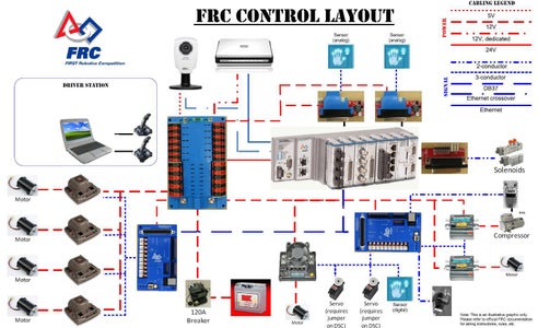
This tutorial will teach you about each of the components in a FRC control system. For each component, I will describe its role in a robot’s electrical system and how it connects to other components.
This tutorial was made through the Autodesk FIRST High School Intern program.
Prerequisites:
A willingness to learn
Photo Credits:
http://team358.org/files/programming/ControlSystem2009-/
http://files.andymark.com/Beta-2010-electronics.jpg
Step 1: Terminology

- Digital Signal: A digital signal has only two states: on or off. Robot components that communicate with a digital signal generally do so by varying the frequency at which they alternate between on and off.
- Analog Signal: Unlike a digital signal, which has discrete values, an analog signal’s output has a continuous range of values. Robot components that use analog signals communicate by varying the voltage of the signal.
- PWM Cable: A Pulse-Width Modulation (PWM) cable is a cable commonly used to allow robot components to communicate with each other, using either digital or analog signals. Most commonly, they have three wires, but there exist versions with anywhere from one to 5 cables.
- CAN: In FRC, a Controller Area Network (CAN) is used to control motor controllers. Several motor controllers are connected serially to the same network and then controlled from the central processor.
- Encoder: An encoder is a sensor used to measure rotation. It uses a digital signal to communicate that the shaft it is attached to has rotated a certain amount – “1 count.” The number of counts per full revolution varies between encoders, but can be anywhere from one to one thousand per revolution.
Step 2: The CRIO


The cRIO is the central processing unit of a FRC robot. Using code generated in LabVIEW, C++, or Java, it takes inputs from the drivers and sensors and outputs instructions to motors, pneumatic solenoid valves, and other devices. While its operation can be as simple as mapping joystick values to motor speeds, it can also execute complex control loops and automated commands. The cRIO is modular, allowing teams to customize it to suit the needs of their robot.
There are two versions of the cRIO that teams may encounter. The cRIO-FRC is shown in the first picture and the cRIO-FRC II is shown in the second. The only practical difference between these two versions is the number of modules they support. The cRIO-FRC supports eight modules, while the cRIO-FRC II supports four. This smaller number of supported modules also translates to a lighter cRIO with a smaller footprint. The cRIO-FRC II was given to rookie teams starting in 2012, with veteran teams having the option to purchase one.
As the metaphorical brain of the robot, the cRIO connects with many different parts of the control system. Its swappable modules can be used to connect it to the Digital Sidecar, the Analog Breakout, and the Solenoid Breakout. The cRIO is powered by a 24V connection from the Power Distribution Board. It connects to the D-Link Router with an Ethernet cable allowing it to communicate with other components connected to the Router, as well as wirelessly with the Drive Station. Finally, the cRIO has a serial port which can be used to connect with the Jaguars through a CAN bus, which is one option for controlling the Jaguars.
Photo Credits:
http://www.chiefdelphi.com/media/photos/31871
https://decibel.ni.com/content/docs/DOC-19103
Step 3: Control Boards


The Digital Sidecar is a module that acts as a hub for the digital signals that are sent to and from the cRIO. The signals it receives are sent from sensors that output digital signals, such as an encoder or the pneumatic pressure switch. The signals it sends are used for controlling devices such as motor controllers or servo motors.
The Digital Sidecar connects to a cRIO module with a DB37 ribbon cable. It connects to sensors, Jaguar and Victor motor controllers, and Spike relays via PWM cables. It is powered by a 12V connection to the Power Distribution Board, and powers the Signal LED with a 2-pin PWM cable.
The Analog Breakout is a module that allows the cRIO to take analog signals as inputs. Analog inputs are used with sensors such as potentiometers and Infrared rangefinders. In addition, it also provides an option to measure battery voltage from one of the analog inputs.
The Analog Breakout connects directly to the cRIO NI 9201 analog input module. It receives power from a 12V connection to the Power Distribution Board, and receives data from sensors via PWM cables.
The Solenoid Breakout is a module that allows the cRIO to control the solenoid valves used in pneumatic systems. It can power 12V or 24V solenoids, but only one type at a time.
The Solenoid Breakout connects directly to the cRIO NI 9472 digital sourcing module. It receives power either from a 12V connection to the Power Distribution Board, or from the 24V power that is also supplied to the cRIO. The Solenoid Breakout sends commands to solenoid valves via 2-pin PWM cables.
Photo Credits:
http://www.usfirst.org/sites/default/files/uploadedFiles/Robotics_Programs/FRC/Game_and_Season__Info/2012_Assets/Digital%20Sidecar.pdf
http://www.usfirst.org/sites/default/files/uploadedFiles/Robotics_Programs/FRC/Game_and_Season__Info/2012_Assets/Analog%20Breakout.pdf
http://www.usfirst.org/sites/default/files/uploadedFiles/Robotics_Programs/FRC/Game_and_Season__Info/2012_Assets/Solenoid%20Breakout.pdf
Step 4: Power Distribution


A 12 volt lead acid battery provides power for all electrical systems on an FRC robot.
The positive terminal of the 12V battery connects to 120 Amp Circuit Breaker, while the negative terminal connects directly to the Power Distribution Board.
The 120 Amp Circuit Breaker is the robot’s on/off switch. It also limits the current draw of all electronics on the robot to 120A, though this limit can be broken for short periods.
The 120 Amp Circuit Breaker takes a direct connection from the positive side of the robot’s 12V battery at one terminal and connects it to the positive terminal of the Power Distribution Board.
The Power Distribution Board distributes power from the 12V battery to all of the different components on the robot. It also regulates power draw for each component through the use of 20, 30, and 40 amp auto resetting circuit breakers.
The Power Distribution Board is connected to almost every part of the control system. Its main positive terminal connects to the 120 Amp Circuit Breaker, while its main negative terminal connects directly to the battery. It has 24V connections for the cRIO and a Solenoid Breakout, a 5V connection for a camera, and a dedicated 12V connection for the Router Power Converter. It has eight 12V connections that can draw up to 40 amps of current and twelve 12V terminals that can draw up to 30 amps of current. These terminals connect to many components such as motor controllers, cRIO breakout boards, and even custom circuits.
The final part of the robot’s power distribution system is the Router Power Converter. This component converts the 12V power dedicated to the router and converts it to the voltage necessary for the D-Link Router.
The Router Power Converter connects to the Power Distribution Board’s 12V router connection and to the D-Link Router itself.
Photo Credits:
http://www.batterystore.com/Yuasa/YuasaImages/NP18-12.jpg
http://www.andymark.com/product-p/am-0282.htm
http://www.usfirst.org/sites/default/files/uploadedFiles/Robotics_Programs/FRC/Game_and_Season__Info/2012_Assets/Power%20Distribution%20Board.pdf
http://www.andymark.com/product-p/am-0899.htm
Step 5: Motor Controllers


There are two version of the Jaguar motor controller: one with black plastic and another with gray plastic. The differences between the two versions are fairly technical, so I won’t address them in this tutorial. A Jaguar provides speed and directional control for the motor it is connected to. The most common way of controlling them is with PWM cables, but they can be connected via a CAN bus. Connecting Jaguars through the CAN bus unlocks extra capabilities in the motor controller. For example, a CAN connection would allow a team to connect an encoder to the Jaguar and use its processing power to do closed loop control of speed and position.
The Jaguar motor controller’s main connections are to one of the Power Distribution Board’s 12V outputs and to a motor. While the Jaguar must be wired to the terminals with the correct polarity on the Power Distribution Board, the motor’s polarity can be swapped on the Jaguar’s output. However, doing so swaps the direction the motor turns when given directions from code. In addition, the Jaguar connects to the Digital Sidecar with a PWM cable if PWM control is used, and to the cRIO’s serial port if CAN control is used. Finally, an encoder can be connected to the Jaguar’s 5-pin PWM port for closed loop speed and position control.
The Victor 884 motor controller is very similar to the Jaguar motor controller. Like the Jaguar, it controls the speed and direction of the motor connected to it. However, Victors can only be controlled with PWM cables and are therefore unable to take advantage of the benefits offered by the CAN bus. Still, many veteran teams continue to use Victors because they have a smaller footprint and are considered more reliable.
The Victor motor controller connects to the Power Distribution board through one of its 12V terminals and directly to a motor. It is controlled over PWM by the Digital Sidecar. Finally, a Victor’s cooling fan must be connected with the wires running to the Power Distribution Board.
The Spike relay essentially functions as an on/off switch for components. When used with motors, it can be used to drive them in forward, reverse, or off. The Spike can also be used to turn on or off other electrical devices such as lights or a compressor. Finally, the Spike relay has a port for a 20 amp circuit breaker, in addition to the breaker on the Power Distribution Board.
The Spike connects to one of the Power Distribution Board’s 12V 30 amp terminals. Its outputs can be connected to motors, a compressor, lights, or solenoid valves. It is controlled via a PWM connection to the Digital Sidecar.
Photo Credits:
http://files.chinaaet.com/images/2012/05/08/efdf49ff-fced-45d9-8048-ab8f0730d62c.jpg
http://team358.org/files/programming/ControlSystem2009-/components.php
http://www.vexrobotics.com/products/vexpro/victor-speed-controller.html
http://www.vexrobotics.com/products/vexpro/217-0220.html
Step 6: Miscellaneous


The D-Link Router is powered through the Router Power Converter and connects to the cRIO with an Ethernet cable. The router can also connect to other devices through Ethernet, allowing them to communicate with the cRIO and driver station. The device that most commonly uses this method of connection is an Axis camera.
The Rockwell Signal LED is used to alert people around a robot that it is operational and to communicate additional information about its current state. There are a total of five different blinking patterns used by the Signal LED. Here is a list of the different patterns and what they indicate:
- Steady On: Autonomous mode
- Short Off: (1500ms on, 100ms off): Tele-operated mode
- Slow Blinking (900ms on, 900ms off): Robot disabled
- Fast Blinking (200ms on, 200ms off): System error due to no Driver Station communication, a bad cRIO image, a bad team ID, or many communication errors
- Fast-Slow Blinking (200ms on, 900ms off): Low battery and system disabled by system watchdog, user watchdog, or the Driver Station set to disabled.
There are two cameras that can be connected to the robot for use as a sensor for vision processing, or just as a feedback device for the drivers. Though there are two camera models, the Axis M1011 and the Axis 206, they are functionally equivalent.
The camera receives power from the Power Distribution Board through its dedicated 5V connection. It also connects to the D-Link Router with an Ethernet cable, allowing it to communicate with the cRIO and the Driver Station.
Photo Credits:
http://www.andymark.com/product-p/am-0839.htm
http://raise.rockwellautomation.com/RAConfig/config.asp?cmd=edit&CID=B4E7802D0FE341B89316216E3527C565
http://www.icode.co.uk/icatcher/cctvshop/axis-m1011-network-camera-p-372.html
http://www.vitechsecurity.co.uk/images/axis_206.jpg
Step 7: Driver Station


The Driver Station Laptop is the laptop that controls the robot. Though a Classmate netbook is provided by FIRST for this role, teams have the option of installing the Driver Station software on another laptop if they want to. The Driver Station acts as a dashboard for controlling the robot by providing important information for matches, software development, and debugging. Some teams offload tasks such as vision processing from the cRIO to the Driver Station, allowing the code to run faster and taking the load off of the cRIO.
The Driver Station must be connected to any controls a team wishes to use. These controllers, along with the optional Cypress Board, are connected through a standard USB connection. During the build season, the Driver Station can communicate directly with the robot over Wi-Fi, but must be plugged in through a supplied Ethernet cable during matches at competitions. The laptop is powered by whatever power supply the manufacturer uses. A power connection for the Classmate is also provided during matches at competitions.
The Cypress FirstTouch board is an Arduino powered system on a chip that allows teams to make custom control interfaces for their robot.
The FirstTouch connects to the Driver Station laptop with an included USB cable. It also connects to any custom buttons the team chooses to use using normal electrical cables.
The final component of the Driver Control Station is the controllers themselves. Teams have the option of using virtually any USB powered controller, whether it is one of the included joysticks, an Xbox 360 gamepad, or some other controller of their choosing. Many teams split up the duty of controlling their robot, having one person drive and the other control manipulators. In this case, teams can mix and match their controllers to cater to their drivers’ preferences.
Photo Credits:
http://www.techsmart.co.za/hardware/notebook_and_tablet_pcs/MECER_Classmate_Notebook_review.html
http://team358.org/files/programming/ControlSystem2009-/components.php
http://www.andymark.com/Attack3-p/am-0598.htm
http://ownedgamers.com/wp-content/uploads/2012/04/xbox-360-controller-recovers-stolen-console.jpg
Step 8: Documentation
Hopefully this tutorial has helped you become familiar with the control system used in the FIRST Robotics Competition. If you want to find out more about the FRC control system, the best way to learn is by reading technical documents supplied by FIRST and part manufacturers. I have included some technical and supporting documents from FIRST in the zipped folder attached to this step. The technical documents discuss individual components in greater detail, while the supporting documents describe how they are used together. I hope you find this consolidated resource helpful.


