

Introduction: Controlling Servos Via Bluetooth (RN-42) and LabVIEW


This project uses a chipKIT WF32, LabVIEW, LabVIEW MakerHub LINX, PmodBT2 (RN-42), and PmodCON3 to control two servos from a smart phone. Hopefully, after viewing this instructable, you will know how to control your own robot or other device using bluetooth!
Digilent sells the LabVIEW Physical Computing Kit which includes the chipKIT WF32 and LabVIEW Home Bundle (a specially licensed version of LabVIEW 2014 SP1 specially for the maker community). LabVIEW MakerHub LINX, a free add-on to LabVIEW, also supports various Arduino boards and various other boards as well. Here is a list of the supported devices if you are interested.
If you have LabVIEW Home Bundle and you aren't sure how to install it, check out this Instructable. If you have LabVIEW and want to get started with your microcontroller board and LabVIEW MakerHub LINX, check out this instructable.
Step 1: Materials


1) LabVIEW
2) LabVIEW MakerHub LINX
3) PmodBT2
4) PmodCON3
5) chipKIT WF32
6) 2x Micro Servos
*There are links to all of the products that were not linked in the introduction.
Step 2: Wiring!!


Alright now that we have the parts, we need to assemble them!
Check out the picture above to make sure you have the correct jumper setup. This assures that the board can output the 5V necessary to power the micro servos.
Next, let's wire up the PmodBT2. From the PmodBT2 reference manual, we can see that the first pin on connector J1 is RTS and then all the way to pin 12 the connections are: RX, TX, CTS, GND, VCC, STATUS, ~RST, NC, NC, GND, and VCC again. Since the WF32 does not have CTS and RTS connections, just tie those pins to ground. Next, attach RX and TX according to the secondary UART connection of the WF32 (UART1). In this case, TX of the WF32 is pin 40 and RX of the WF32 is pin 39. Connect TX of the WF32 to RX of PmodBT2 and connect RX of the WF32 to TX of PmodBT2. Stated differently, connect the second pin on PmodBT2 to pin 40 on the WF32 and the third pin on PmodBT2 to pin 39 on the WF32.
Connect pin 7 on the BT2 to pin 26 on the WF32 and connect pin 8 on the BT2 to pin 27 on the WF32. Also, connect the ground and 3.3V connections to the PmodBT2 (don't forget to tie CTS and RTS to ground).
Step 3: Finishing Up the Wiring

Now all we need to do is connect the micro servos to PmodCON3 and then connect the data lines to control the servos. Connect one servo to P1 and the other to P2. Then connect a wire from the first pin on the 6 pin header to digital channel 28 on the WF32 and connect a wire from the second pin on the 6 pin header to digital channel 29 on the WF32. Then, connect a 5V power wire to the positive screw terminal and a ground wire to the negative screw terminal. Connect the 5V to the 5V0 on the WF32 and connect the ground to GND on the WF32.
Ok we're done wiring (finally).
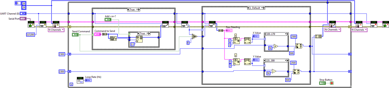
Step 4: LabVIEW Code
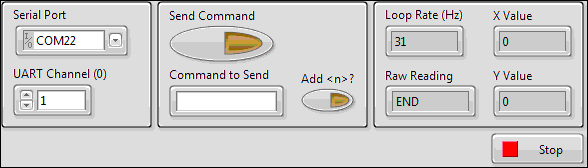
Download the VI below and open it. On the left side of the front panel are the LINX settings. Select your COM port that your board is connected to and use UART channel 1.
The next part on the front panel is where you can send commands to the PmodBT2. Check out the RN-42 datasheet for a list of all the commands. To enter command mode, enter $$$ into command to send and then click send command. If this was successful, you should read CMD in Raw Reading. To leave command mode, toggle the Add button to add a carriage return to the transmission and then type --- into command to send and click send command. If this was successful, you should read END in Raw Reading. When entering commands, you should read AOK in Raw Reading if successful and ERR if unsuccessful.
By default, the RN-42 communicates over UART at 115200 Baud.
Attachments

Step 5: Phone Application and Finishing Explanation


For this project I used Joystick bluetooth Commander on Android (pictured above). Open the application and connect to the PmodBT2. My PmodBT2 was named RNBT - A5CF. Once connected, you should be able to read 8 ASCII bytes in the Raw Data indicator (one empty, six for UDLR, and one end transmission byte).
When the joystick is stationary, the PmodBT2 will read 200 in both the X and Y values. These values range from 100 to 300 depending on the location of the joystick. In the app options, make sure you set data transmission interval to 100 ms and when idle, send data continually (both pictured above).
Depending on the joystick orientation, the servos are moved accordingly. For instance, if the joystick is up and to the left, the servos will turn left and up (one servo for each axis).
You're done! Try using this as a guide to set up your own bluetooth connection.


