Introduction: Convert a ZX82 Spectrum Keyboard Into an Expandable USB Keyboard With Arduino


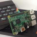

In this Instructable, I'll show you how to convert your ZX82 Spectrum keyboard into a functionally-expandable USB keyboard compatible with anything USB-enabled. This build is compact enough that when you're done, you can fit a Raspberry Pi or other small computer into the spectrum as well and just plug the keyboard in internally.
This build is nice and easy; I'll walk you through building the hardware interface to connect your Arduino to the Spectrum's keyboard membrane. Then we'll talk about how the software driver is constructed piece by piece, so it should be easy for you to customize later.
You will need:
- ZX82 Spectrum (doesn't need to be working) (x1)
- Arduino Leonardo or LeoStick (without soldered headers and preferably Leonardo for starting-out Arduino'ers) (x1)
- Arduino IDE
- Resistors
- 10KΩ (x5)
- Wire (x1 pack)
- Perf board / PCB (preferably tracked, approximately 30x45mm) (x2)
- USB A male-female extender cable (preferably short) (x1)
- Soldering iron, solder and solder sucker (desoldering pen)
- Pliers
- Screwdriver
- Masking tape
- Glue gun
- Multimeter or circuit tester
Step 1: Preparation

Harvest your parts
The good news is getting the bits you need is easy. You will need to harvest:
- The upper and lower casing (with the screws)
- The keyboard connection headers.
First of all, unscrew all the screws on the underside of the Spectrum. Turn it back over and lift the lid, ensuring you don't tug the ribbon connectors. Carefully, but firmly pull the ribbon connectors upward out of the motherboard to remove them. The top half should now be free of the bottom.
We also need the lower case and the keyboard headers off the motherboard. Remove the screws from the motherboard that hold it down. Now you can desolder the headers from the underside of the board. The correct connections are easy to spot; they're the only series of pins arranged horizontally.
Protecting your membrane (REALLY IMPORTANT)
These membranes are some of the most fragile tech I have ever encountered. In their day they were fragile and going on 40 years old they're really fragile. To keep them safe, use masking tape to secure them to the lid of the spectrum without creasing the membrane. If at any point you need to replace the membrane, you can get replacements on eBay. This link is for the ZX82 model.
Ready your Adruino IDE
This step is for those who are opting for the LeoStick. If you are using an Arduino Leonardo you are supported as standard, so you can move on to the next step.
For LeoSticks, you can find all the information you need to get it going with your Arduino IDE at the LeoStick link provided. You'll need to follow the instructions to add the supporting library to the Arduino IDE and then try uploading a program to check it uploads properly. When it does, you too are ready.
Step 2: Building the Keyboard Hardware Interface


The Arduino LeoStick has caught my eye for a while; it's very compact and has the USB connection on the PCB - really handy! That makes it perfect for a tight space. Alternatively, the Arduino Leonardo would work just as well and is supported by the Arduino IDE as standard.
To find out how the keyboard connections worked, I found this schematic (scroll to the 'Keyboard Scanning' heading), which basically gives me the following pieces of information:
- The film with 5 contacts has the Data lines
- The Data lines have pull-up resistors to +5V
- The film with 8 contacts has the Address lines
- The Keyboard is arranged in a 5x8 matrix (Data x Address)
I'll tackle how a matrix works in the next section as I cover writing the software, suffice it to say that the important thing now is that the data lines are individually held high. All this information is diagrammatically represented in the first diagram above.
Wiring to the Arduino
I have included the pin order for you to connect the Arduino pins in the above diagram. I recommend soldering the wires and resistors first, then placing the PCBs down where you are going to have them (ideally they'll sit in the top recess of the lid). That way you can ensure that the connectors' metal contacts are on the side of the membrane that has the exposed connections before you solder them. The placement of the connections needed to be flexible so as not to tug or stress the keyboard membrane.
Cut down two blank prototyping PCBs to be big enough to attach the keyboard connectors, plus the resistors and wires to the Arduino. The 30x45mm suggested should be a good fit. When you do this, leave your Arduino wires longer than you need. You can shorten them once you've sorted out the placements of everything. My PCBs with ZX Spectrum connectors are shown above in the second image. The resistors on the data PCB (green, right) all connect from the connector to the yellow 5V wire at the top of the PCB.
The blue address lines are the ones changed by the controller (our independent variable) and the green data lines are the ones tested (our dependent variable). So, the address lines connect to the digital pins (marked with numbers 0-13) and the data lines are connected to the analog input pins (marked A0-A4) in the above sequence.
In the third image, the PCBs are just placed in an Arduino Uno so that you can see what it looks like wired up. If you use the Leonardo, the pin layouts for the Leonardo and Uno are the same, so you can copy this exactly. You can see the data lines in green going to the A0-4 pins, the blue address lines going to the D2-9 pins and the yellow +5v wire going to a VCC connection. Use digital pins 2-9 rather than 0-7 because digital pins 0 and 1 are used for the serial connection (Tx and Rx) which will be used by the USB connection. As such, leave digital pins 0 and 1 unconnected(use pins 2-9). Once soldered to the LeoStick and laid into the lid, your Spectrum-USB Arduino keyboard adapter should resemble the fourth image. Note that the ribbons aren't connected just yet.
Testing the connections
At this stage, test your soldering by setting all the pin numbers (<pin>) to output for both the analog and digital pins:
pinMode(<pin>, OUTPUT);
and then set them to +5V:
digitalWrite(<pin>, HIGH);
That way, you can run over all the keyboard connections in the connectors (and the +5V side of the resitors) with a multimeter and check each for +5V, ensuring good connections. Once happy, fix the PCBs in line with the membrane connections using a glue gun as shown in the final images above. When they are secure, then you can carefully plug the membrane back in. Since the membrane is so delicate, keep the films as sheltered and uncreased as possible by gently packing them into the more spacious top section of the upper case as shown. The masking tape will gently hold them flat so as to control flexing and minimise movement while the case is opened and closed. That's the hardware ready to go!
Step 3: Building the Keyboard Arduino Software

First I'll run through matrices so you can see the theory and then I'll show you how the driver is written using the Arduino IDE. If you are a confident coder and want to skip this, you can get a copy of the complete code on the resources page of my website, AltoidsDrone.com.
To recap, the key information for writing the program that we gathered in the last step was:
- The film with 5 contacts has the Data lines
- The Data lines use pinsA0-A4 and have pull-up resistors to +5V
- The film with 8 contacts has the Address lines and uses digital pins 2-9
- The Keyboard is arranged in a 5×8 matrix (Data x Address)
How a keyboard matrix works
A keyboard matrix is a grid of wires, such as the Address and Data lines forming the 5x8 grid in the Spectrum. Each Key is a button that intersects one row with one column (the crosses on the grid) and all the buttons are physically held open by default. This means that the rows and columns are not connected and no current (or voltage) is passed from a row to a column or vice versa.
There are two types of matrix, pull-up and pull-down. You can find out more about the operational differences here. The original Spectrum keyboard used a pull-up configuration. The thing to remember is that on is low in our matrix, not high. So when a key is pressed it is a low voltage that we need to trigger and then look for. The first image shows how the matrix actually works.
In the above four grids, the button connecting the second column to the second row is pressed. To start with, everything is held high. The first column is changed to low, and the controller checks the voltage at each row to see if there is a drop (first grid). No buttons on that column are pressed so all rows stay at 5V. The first column returns high, and the second column is sent low (second image). The rows are sequentially checked again. The pressed button on the second row is connecting the +5V supply of the second row to the 0V of the second column via the resistor (third image). The controller detects the 0V on that row and knows that the second button of the second column is the letter 'j' so outputs a 'j' keystroke. The cycle then carries on down the rows and along the columns, then repeats (fourth image).
In a nutshell, that's how a matrix works. So, in practice all our keyboard driver has to do is perform the same cycle of lowering each column and sequentially checking the rows on that column for 0V. Then it can look-up which keystroke to output to the USB.
Writing the software
I'm providing the complete software driver here for you to look at as we run through putting it together. If you are new to coding for Arduino, have a blank sketch open and you can put the code together as we go. This tutorial is also available with full syntax-highlighting through this link.
What this program will give us is the letters A-Z in upper and lower case, the numbers 0-9, a SPACE, BACKSPACE, CAPS-LOCK and RETURN. This covers the basics of what you'll need to use a computer; believe me, with a tiny space button in the bottom corner, you wouldn't want to do word processing on this keyboard. All our keys will be wired in and accounted for so if you do want to make every function on the keyboard work, you can add them into the program later.
Fiirst, change your Board to the Leonardo, or the LeoStick. Go to Tools > Board and select the one you are using.
We'll start with the basic sketch structure:
void setup()
{
}
void loop()
{
}
Above the setup(), we need to declare our variables and write our key mapping data.
const int dataNo = 5;
const int addressNo = 8;

int dataPin[dataNo] = {A0,A1,A2,A3,A4};
int address[addressNo] = {2,3,4,5,6,7,8,9};

char keyMap[dataNo][addressNo][2] =
{//    2         3         4         5         6         7         8         9   << address lines
  {{'b','B'},{'h','H'},{'v','V'},{'y','Y'},{'6','6'},{'g','G'},{'t','T'},{'5','5'}},       // A0
  {{'n','N'},{'j','J'},{'c','C'},{'u','U'},{'7','7'},{'f','F'},{'r','R'},{'4','4'}},       // A1
  {{'m','M'},{'k','K'},{'x','X'},{'i','I'},{'8','8'},{'d','D'},{'e','E'},{'3','3'}},       // A2
  {{' ',' '},{'l','L'},{'z','Z'},{'o','O'},{'9','9'},{'s','S'},{'w','W'},{'2','2'}},       // A3
  {{' ',' '},{' ',' '},{' ',' '},{'p','P'},{'0','0'},{'a','A'},{'q','Q'},{'1','1'}}        // A4
};
The integers 'dataNo' and 'addressNo' specify the numbers of rows and columns respectively. As such, the 'KeyMap' character array is 8 across by 5 down (matching our keyboard membrane connectors) and two deep for upper and lower case. The 'dataPin' and 'address' arrays match our soldered pin numbers and are used to easily setup and use the keyboard connections (or easily modify them without changing the functional code). The blank spaces at the bottom are the SPACE (A4, 2), RETURN (A4, 3), BACKSPACE (A3, 2) and CAPS-LOCK (A4, 4).
Note: This driver will work for any keyboard matrix. All you need to do for a different keyboard is set the size variables, pins and key map for your keyboard in the above code. The rest will work as is. If you are using a pull-down configuration, simply swap all the HIGHs and LOWs over, which we'll come to soon.
Now we just need to declare a few more variables for our program logic. The boolean variable, 'wasReleased' will help to ensure that the keyboard outputs one keystroke per press, giving you 'n' instead of 'nnnnnnnnnnnnnn'. Pop these in directly below the above code.
boolean wasReleased = true;
int reRelease = 0;
int capital = 0;
We can now move into the setup() section of the sketch. In this section we need to setup the pins and put them into a ready state if required, then initiate our keyboard function. Rather than specifying each pin individually, we can use for loops to save repetition, hence the above arrays, 'dataPin' and 'address' contain our pin numbers that we can refer to here. The first loop cycles through our digital pins (the address lines). These are the ones we set to HIGH or LOW, so we declare each as an output and set it to its default HIGH state.
  for (int a=0; a<addressNo; a++)
  {
    pinMode(address[a], OUTPUT);
    digitalWrite(address[a], HIGH);
  }
Likewise, the second loop runs through the analog pins (our data lines) and declares each as an input.
  for(int d=0; d<dataNo; d++)
  {
    pinMode(dataPin[d], INPUT);
  }
Finally, we initiate the USB interface for use as an interface device.
Keyboard.begin();
That's the end of our setup() section. We can now move on to the loop(), where the remainder of the code will reside. As we go, I'll put '...' where the next chunk of code will go. The loop() will cycle the address lines and check the data lines, then output the appropriate keystroke. Basically, we will again use for loops with the following structure:
A for loop to cycle the address lines, which cycles the address line it is using LOW at the start and back to HIGH at the end:
  for (int aCyc=0; aCyc<addressNo; aCyc++)
  {
    digitalWrite(address[aCyc], LOW);
    ...
    digitalWrite(address[aCyc], HIGH);
  }
While the address line is low, we need to run through the data lines to see if any of them are low, indicating a button press. So, where the '...' is, we will use another for loop.
    for(int tData=0; tData<dataNo; tData++)
    {
      ...
    }
We now need to read Each data line. A pressed button will send the data line LOW, which in binary is the integer 0 (and thus, HIGH would be a 1). As such, the integer 'pressed' is assigned the binary value of the data line. We can then test that value with the if() statement of 'if(pressed == 0)'. The 'reRelease' integer is incremented to keep a count of how many data line checks are performed between button presses, enabling us to see if all the keys are released before allowing more keystrokes.
      int pressed = digitalRead(dataPin[tData]);
      if(pressed == 0)
      {
        ...
      }
      reRelease++;
At this point we enter into a key press being detected. A keystroke should only be allowed once per button press (if it is the first for that button press), giving us 'n' and not 'nnnnnnnnnnnnn'. Therefore, we test the boolean 'wasReleased' using another if() statement.
        if (wasReleased == true)
        {
          ...
        }
        Keyboard.releaseAll();
        if(capital > 1) capital = 0;
        wasReleased = false;
        reRelease = 0;
Whether or not we send a keystroke through the USB, we need to do some housekeeping here. The 'Keyboard.releaseAll()' method ensures that any keystrokes being sent to USB are discontinued. The 'capital' integer shifts places on the innermost position of the 'keyMap' array. As such, if it is being pressed for a second time to toggle off, it must be reset to the lowercase position of 0. Lastly, if a key press has been detected, the program needs to lock out of sending more keystrokes until all keys have been released. Consequently, the 'reRelease' count must be reset to 0 and our 'wasReleased' set to false.
Assuming, the current cycle is the first of this key press (so 'wasReleased' is true), we come to registering our keystroke to the USB.
          if((aCyc == 2) && (tData == 4)) capital++;
          else if((aCyc == 0) && (tData == 3)) Keyboard.write(KEY_BACKSPACE);
          else if((aCyc == 1) && (tData == 4)) Keyboard.write(KEY_RETURN);
          else Keyboard.print(keyMap[tData][aCyc][capital]);
Special characters, CAPS-LOCK, BACKSPACE and RETURN don't fit into an array of characters and so must be handled individually. As such, each has an if() statement pointing to the specific combination of address and data for that key. The first line increments 'capital' to shift the case position when the CAPS-LOCK is used. The 'else' on the next line means that the CAPS-LOCK is CAPS-LOCK and not SHIFT; this matches the button label and greatly simplifies our key press logic. If the key press is a letter, number or space, the last line references the current data number, address number and capital state to select the appropriate letter from our key map.
Finally, the last thing that we must do is re-enable our keystrokes if all the keys have been released, so this chunk goes before the final '}' at the end of the loop().
  if (reRelease > (dataNo*addressNo))
  {
    wasReleased = true;
  }
This simply checks that our 'reRelease' count is greater than the size of the 'keyMap' array (and so has got passed the key it detected last time). If so, it changes 'wasReleased' to true, re-enabling keystrokes to be sent to USB.
That's the complete keyboard driver. Simply connect the Arduino to the computer via USB and upload the sketch to your arduino. Once rebooted, you should immediately be able to type using the Spectrum's old rubber keyboard.
To see how I got this into my Spectrum along with a Raspberry Pi, built-in Wifi and VGA support checkout this link at AltoidsDrone.com.
Acknowldgements:
- Many thanks to 1000bit.it for their schematics and comprehensive guide to the vintage computer world.