

Introduction: Create Your Own VR Game Controller Using Arduino


If you are a gamer and a hardware geek at the same time, you obviously know how hard it can be to choose how to spend weekend, playing games or making cool hardware. This project will give you heaven of the both worlds!
We will create an Arduino based game controller which detects motion which works as a great controller for VR games. But it's not limited to VR, it can be used to play any supported PC, XBox or PlayStation game.
Required Hardware:
- Arduino Uno
- MPU6050
Step 1: Programming Arduino
If you are not interested in details how the program works then simply upload the code given in resources.zip to Arduino Uno and jump to Step 2.
_
Initializing Sensor
To initialize the sensor, we first initialize the I2C communication using standard Wire library then configure the MPU. If configuration fails, then the Arduino goes in forever while loop as it’s useless to continue.
void InitializeMpu()
{
  Wire.begin();
  Wire.setClock(400000UL);
  i2cData[0] = 7; // Set the sample rate to 1000Hz - 8kHz/(7+1) = 1000Hz
  i2cData[1] = 0x00; // Disable FSYNC and set 260 Hz Acc filtering, 256 Hz Gyro filtering, 8 KHz sampling
  i2cData[2] = 0x00; // Set Gyro Full Scale Range to ±250deg/s
  i2cData[3] = 0x00; // Set Accelerometer Full Scale Range to ±2g
  while (i2cWrite(0x19, i2cData, 4, false));   // Write to all four registers at once
  while (i2cWrite(0x6B, 0x01, true));   // PLL with X axis gyroscope reference and disable sleep mode
  while (i2cRead(0x75, i2cData, 1));
  if (i2cData[0] != 0x68)
  { // Read "WHO_AM_I" register
    Serial.print(F("Error reading sensor"));
    while (1);
  }
}
Reading the Motion Data
Motion data is read from IMU sensor (MPU6050) in every loop and the respective gyro and accelerometer values are updated. The following function does this job.
void UpdateReadings()
{
  while (i2cRead(0x3B, i2cData, 14));
  accX = ((i2cData[0] << 8) | i2cData[1]);
  accY = ((i2cData[2] << 8) | i2cData[3]);
  accZ = ((i2cData[4] << 8) | i2cData[5]);
  tempRaw = (i2cData[6] << 8) | i2cData[7];
  gyroX = (i2cData[8] << 8) | i2cData[9];
  gyroY = (i2cData[10] << 8) | i2cData[11];
  gyroZ = (i2cData[12] << 8) | i2cData[13];
}
Computing Angles Using Complementary Filter
Angles can be computed using complementary filter with a good accuracy. We will use complementary filter since it’s fine for most of the application. But if you need even better accuracy, you can use Kalman Filter.
void ComputeAngles()
{
  double roll  = atan2(accY, accZ) * RAD_TO_DEG;
  double pitch = atan(-accX / sqrt(accY * accY + accZ * accZ)) * RAD_TO_DEG;

  double gyroXrate = gyroX / 131.0; // Convert to deg/s
  double gyroYrate = gyroY / 131.0; // Convert to deg/s

  compAngleX = 0.98 * (compAngleX + gyroXrate * dt) + 0.02 * roll; // Calculate the angle using a Complimentary filter
  compAngleY = 0.98 * (compAngleY + gyroYrate * dt) + 0.02 * pitch;
}
Set Controller Data Object
We need a dataForController_t object to send data to the computer/host as a joystick. We use the following code to create and fill dataForController_t object.
dataForController_t getControllerData(double _roll, double _pitch)
{
  //Restrict roll and pitch to +-90
  if (_roll > 90 || _roll < -90)
    _roll = 90 * _roll / abs(_roll);

  if (_pitch > 90 || _pitch < -90)
    _pitch = 90 * _pitch / abs(_pitch);

  //Get new instance with default values of buttons and sticks
  dataForController_t controllerData = getBlankDataForController();

  controllerData.rightStickX =  (int)(_roll * 1.42 + 128);
  controllerData.rightStickY = (int)(_pitch * 1.42 + 128);

  //You can use these and many other buttons also
  //  controllerData.triangleOn = !digitalRead(2);
  //  controllerData.circleOn = !digitalRead(3);
  //  controllerData.squareOn = !digitalRead(4);
  //  controllerData.crossOn = !digitalRead(5);

  return controllerData;
}
In loop() we will call this function as,
dataForController_t controllerData = getControllerData(compAngleX, compAngleY);
Send Controller Data to Computer
To send this data to joystick simple call the setControllerData() function as follows,
setControllerData(controllerData);
Attachments

Step 2: Connect the MPU Sensor
Connect the MPU sensor with Arduino Uno as,
Arduino MPU6050
3.3V ————- Vcc
Gnd ————- Gnd
A5 ————— SCL
A4 ————— SDA
After you have programmed your Arduino Uno with the given code, connect the MPU. You can uncomment the following line to check on serial monitor/plotter if everything is working fine, moving the sensor will change the values accordingly. Be sure to comment it again after testing.
//#define DEBUG
Step 3: Turn Arduino Into Joystick

To turn Arduino into joystick first you need to turn start Arduino into DFU mode. To do this, just connect the pins mentioned in the image.
On Windows the Arduino (usb device) will disconnect with a sound (be-dun). And connect again (buh-din!). Now Arduino is on DFU mode, just open the TurnIntoAJoystick.bat file (see resources section) and it will turn your Arduino into a joystick.Atmel FLIP must be installed for this to work. In windows 10 go to Settings > Devices > Connected Devices and it will show up as a Joystick.
Step 4: Testing the Joystick
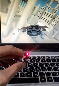
You can test the joystick using TestJoystick.exe (see resources section). Just connect the Arduino Joystick into your computer and run TestJoystick.exe. It will show a floating plane that rotates as you move the joysytick. You can add more buttons and features and use it the way you like. For more information check out the UnoJoy page.
If it works fine then go ahead and try it with your favorite games!
Attachments

Participated in the
Lights Contest 2017

Participated in the
Microcontroller Contest 2017


