

Introduction: Custom Mouse Wheel As PocketNC Jog Wheel (or Volume Control Dial)


This Instructable explains how to use an Arduino and a rotary encoder to make your own mouse wheel and how to design an enclosure for it using Fusion 360. It also explains how to use your mouse wheel as a jog wheel for the Pocket NC. If you don't have a Pocket NC, the design and Arduino portions can still apply to you if you're interested in making a mouse wheel (or use it as a volume control dial or bind keyboard and mouse events to it). If you like it, please consider voting for it in the 3D Printing, Arduino and CNC Contests!
The Pocket NC is a 5-axis desktop CNC machine made by a Bozeman-based company also called Pocket NC. The Pocket NC is an amazing piece of machinery. It's the only 5-axis milling machine on the market under $60,000 and the Pocket NC rings up at a fraction of that at only $4,000. It was successfully kickstarted a couple years ago and they're now going strong, having already completed a second kickstarter for a different machine while continuing to make Pocket NCs. If you own a Pocket NC, you know just how awesome it is, but there are a couple quirks about it that leave you wanting more. First, it doesn't have a jog wheel, which isn't a huge deal, but not having to worry about misclicking the jog button on the screen while your attention is on the material or tool would be very convenient. Second, its user interface is the default interface, called Axis, provided by the open source project LinuxCNC. To get it to run, you either need to hook up a keyboard, mouse and display to the machine (the easiest method), or enable X forwarding over ssh to your computer which has different issues on every OS. The most awesome part about the Pocket NC is its form factor and having to hook up a display, keyboard, and mouse adds some undesired bulk to the workbench, while also adding the hassle of having to transfer gcode over USB sticks. Hooking up to your own laptop is ideal, but the problems with X forwarding can be especially frustrating. In this tutorial, I'll show you how to address both of these issues by installing a new user interface on the Pocket NC that works through your web browser and also allows you to use your mouse wheel as a jog wheel. We'll create our own USB mouse wheel that is more reminiscent of a jog wheel. We'll start by designing an enclosure in Fusion 360, where I'll walk you through some parametric modeling. Then we'll 3D print the main enclosure, laser cut a top and bottom for the enclosure and assemble the electronics of the jog wheel. The brain of the mouse wheel will be an Arduino, which I'll show you how to code so it will send the mouse wheel events over USB. Finally, I'll show you how to back up your Pocket NC, then how to install the new user interface.
Step 1: What You'll Need


Below I've listed what I used for this project, but throughout the tutorial I explain how an alternative could feasibly be used. Feel free to reach out with questions for more details if you'd like to go with something else.
Tools
- 3D Printer - I used my Makerbot Replicator 2.
- Laser Cutter - I used a friend's Epilog Mini, but I hope to get my Glowforge soon. If you preorder a Glowforge after using this link you can get $100 off.
- Sand paper - I used a quick pass of 150 grit sand paper to get rid of the scorch marks from the laser cutting. You could also use painter's tape to cover the wood before laser cutting, but a quick sand looks better either way.
- Screw driver - My screws were Philips heads, but if you go with a different head, you'll need something else.
- Wire strippers - These are for attaching wires to your rotary encoder.
- Soldering Iron - You can get cheaper ones than this one, especially for the purposes in this tutorial, but this is the one that I own and it works great. I use it to heat threaded inserts into the 3D printed plastic.
- Pocket NC - If you plan to use this as a jog wheel, you'll need to have a Pocket NC! I'd love to get this working on other CNC machines, such as a Shapeoko, Nomad and others, but I'd need to get my hands on them first.
- Micro SD Card Reader - If your computer doesn't have a SD Card Reader, you'll need one of these.
Materials
- 3D Printing Filament - I used black Hatchbox PLA, but use whatever you like!
- 1/8" Plywood - I like using wood, but there's no reason you couldn't use acrylic, MDF or anything else.
- Threaded inserts - These are the inserts that I designed for and used.
- M3 x 12mm screws - We use these to attach the laser cut plywood to the 3D printed enclosure.
- Pololu A-Star 32U4 Mini LV - This Arduino compatible board sports the same chip as the Arduino Micro and Arduino Leonardo and allows you to easily mimic a keyboard or mouse.
- Micro B to A USB cable - This will connect the Arduino to your computer.
- Rotary Encoder - There are a number of options to choose from, but I chose this one because of its 100 detents per full rotation.
- Breadboard - For connecting our circuit.
- Jumper Wires - We'll wire up our circuit with these.
- Rubber Feet - These ones are self-adhesive so they just stick on the bottom when we're done.
- Micro SD Card (4GB or larger) - You'll need this if you plan on following my instructions on backing up and flashing your PocketNC. This one comes with a MicroSD to SD Card adapter so many computers will be able to read and write to the MicroSD card. If you don't have an SD Card reader, pick up the USB Micro SD Card Reader linked above under Tools.
Step 2: Parametric Design
If you are familiar with what parametric design is, feel free to skip to the next section. For completeness, I want to take a minute to explain what parametric design is and why it is beneficial when designing parts.
There are essentially two ways to design a 3D model, direct modeling or parametric modeling. Direct modeling involves creating shapes and features specific to a design. You can perform all the same operations that you would in parametric modeling such as extrude or loft or boolean operations such as union or intersection, except you do so without concern for making changes to the design in the future. You can model very quickly because you don't need to think about how the design might change. Instead, you can focus on this design and do whatever it takes to get it the way you want. Parametric modeling, on the other hand, requires performing operations in a certain order and is very forward looking in nature as your design allows for changes in certain dimensions to be made. Relationships between certain dimensions are made to ensure that if one changes, the other can change accordingly. As long as the changes that you allow in your model are the only ones that need to be changed, you can very quickly iterate on the design or visualize changes before manufacturing your design. If unexpected design changes need to be made, it can be just as difficult to change a parametric design as a directly modeled design.
Here's a quick example to explain the difference. Let's say we need a simple faceplate, which is just a rectangular piece of material with holes in each corner. The one we need for our current design needs to be 4 inches square with the holes 1/2 inch in from from each corner. The designer figures he just needs this one design and quickly models it by creating the 4 inch square then manually places the center of the holes at (.5, .5), (3.5, .5), (.5, 3.5) and (3.5, 3.5). It's quick and easy and the design is done. Now let's say that the spec for the faceplate changes for some reason, and instead it's now 6 inches x 5 inches and the holes need to be 3/8" in from the corners. The design from before doesn't help us, as we need to perform all the steps over again from the beginning as all of our dimensions have changed. The model is so simple, it may not matter in this case, but a better way to have designed the model from the start would have been to define 3 variables, width, height and hole offset. Then a rectangular solid could be created using width and height and the holes could be placed at (hole_offset, hole_offset), (width-hole_offset, hole_offset), (hole_offset, height-hole_offset) and (width-hole_offset, height-hole_offset). Now if any of those variables change, the model is updated and you have a new part. In the video above, notice how fast I was able to make the 4 x 4 plate with holes. I then make everything parametric, which takes a longer to set up, but once done can easily be tweaked how we want it.
The example above is very simple and the equations are easy enough to write out, but as parts get more complex figuring out the equations can be quite complicated. Good CAD software can quickly and easily define those kinds of relationships without needing to know the underlying equations. I'm a huge fan of parametric modeling because once a design is implemented it allows you to quickly adjust dimensions to suit your needs. It can take more time to properly design a parametric model, but it will save you time in the long run if you plan on doing several iterations of the design, or just want quick visualizations of what the design could be. I use OpenSCAD and OpenJSCAD often which are pure coding interfaces to 3D modeling. I love to code and am good at figuring out all the equations and variables to use, so using them for parametric modeling is a good fit for me. The coding can be a pain, though, and poorly written or poorly commented code can be a mess to debug and modify. CAD software provides a visual interface for setting up many of the relationships suited to parametric modeling, which can make the design process go much faster. I've been meaning to learn Fusion 360 for a while now, especially because of its integrated CAM software and 5-axis machining capabilities at the low, low cost of FREE (as long as you make under $100,000 with it). In the next section, I'll take you through the steps I took to design my enclosure. I'll show you how to take advantage of the parameters window and the dimension tool to ensure everything is parametric in nature.
Step 3: Choice of Rotary Encoder
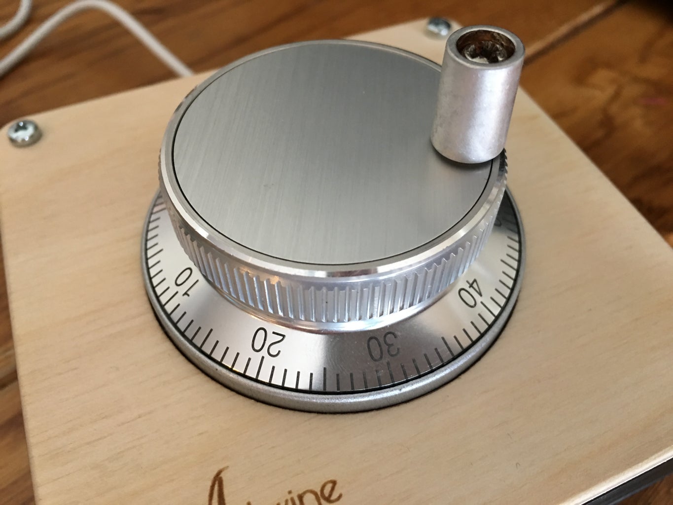

A jog wheel is a dial that can be turned to make your CNC machine move on a given axis. In electronics, the device that is capable of this is called a rotary encoder. I'll talk a little more about how a rotary encoder works later on when we start programming our jog wheel, but it's important to talk about the form factor of our device so we can design a spot for it in our enclosure. There are many different kinds of rotary encoders at different price points. You can get cheap rotary encoders anywhere from under $1 to up to $4. They come as a simple panel-mount dial that can easily mount into an adequately sized hole using its provided hex nut. The problem with cheap rotary encoders is they often have an inconvenient number of detents (notches that you can feel when you turn the dial). For example, this Amazon listing, is for 3, 6mm rotary encoders with 18 detents for about $2. When using a rotary encoder as a jog wheel, it's nice to have 100 detents per rotation so you can set the amount the machine will step to a power of 10, such as .1, .01, or .001 and it's easy to know how much you'll rotate in one full rotation. At 18 detents per revolution and step size of .01, it would take a little more than 5 and half rotations to move an inch -- not so precise. At 100 detents per revolution and a step size of .01 it would take 1 full rotation to move 1 inch, much better! The problem is 100 detent rotary encoders are more expensive. This is the one that I will be using. Instead of being panel mount with a hex nut and a knob that is placed on top, this one has the whole assembly made and mounts using 3 threaded screws from the bottom. In the following steps, I'll point out what you would change if you wanted to go with a cheaper encoder.
Step 4: Enclosure Design With Fusion 360


This is my first time using Fusion 360, so there are probably more efficient workflows and I appreciate any suggestions or other feedback. I kept the design simple so it could be created in a number of different ways. I chose to 3D print the middle part and laser cut the top and bottom plates. The whole thing could be milled or entirely 3D printed, or laser cut. You could even forget this specific design and use standoffs between two pieces of plywood that were cut out with a jigsaw or just breadboard the whole thing without an enclosure. All the files are provided here for your reference and the video below will take you through the steps I took in Fusion 360 to make this design.
I enjoy using OpenSCAD and OpenJSCAD to create my designs so I think a lot in terms of variables and equations. In the video below, I often take advantage of the Parameters window, using equations and variables as I go. You can follow along, open up the Fusion 360 file I created, or just download and 3D print the STL file:
- Fusion 360 f3d file - Has a timeline that you can step through to see everything that I did in the video and make changes of your own.
- Enclosure STL file - Download this to just 3D print your own.
- Top and Bottom SVG - SVG file of the top and bottom for laser cutting.
- Top and Bottom PDF - Same file as above, but in PDF form for easy printing.
- Top STL - In case you want to 3D print it instead of laser cutting.
- Bottom STL - In case you want to 3D print it instead of laser cutting.
After designing and exporting the enclosure, I 3D printed the middle and laser cut the top and bottom. I have a MakerBot Replicator 2 that I used to do the 3D printing. I used a friend's Epilog laser cutter to cut the top and bottom. I used a soldering iron to heat threaded inserts into the 3D printed part so that I could attach the top and bottom using M3 screws. If you decide to machine the part rather than 3D print it, you could tap threads into the holes instead, just make sure to size the holes to suitable dimensions for your tap.
Step 5: Assembly


Assemble the enclosure as shown in the pictures above. Attach the threaded brass inserts by using a soldering iron to heat them into the holes we designed into the part. Then attach the rotary encoder and top laser cut plate. Next we need to wire up the Arduino to the encoder. The Arduino compatible board that I used is the Pololu A-Star 32U4 Mini LV. Because it uses the Atmega 32U4 chip it can easily be programmed to be a mouse or keyboard. You could also use an Arduino Leonardo, Arduino Micro, or a Makey Makey to name a few. The important part is that you wire up your encoder to the hardware interrupt pins 2 and 3. In the next step we'll go over what we need those two pins for. Your encoder will also have a ground pin, often the middle pin that you'll need to wire up to GND on your Arduino. It may also have a VCC pin that you should wire up to 5V on your Arduino. If you don't have a VCC pin, then we'll just activate the built in pull-up resistors on your Arduino. Follow the images above to assemble everything from the enclosure, to wiring up the encoder. In the next step, we'll go over how to program it (which you may want to do before completing assembly to make sure everything is wired correctly). The last step is to put everything into the enclosure and attach the bottom plate, then stick rubber feet to the bottom to help keep it stationary.
Step 6: Arduino Programming
We'll get to the code below, but first here's some information about how a rotary encoder works. We'll need this information when implementing our mouse wheel code below. A rotary encoder outputs two signals, A and B, in a certain pattern that allows you to determine which way the knob is being turned based on the previous and current state of the two pins. So, whenever either signal from the rotary encoder changes we want to know about it. Hooking up the encoder to our interrupt pins allows us to do that. No matter what the Arduino is currently doing, a change on either of the interrupt pins will trigger a specific chunk of code to run. In that chunk of code we compare the previous and current states of the pins and increment or decrement a counter variable to indicate which direction we turned the knob.
On my blog is an interactive widget that demonstrates the behavior of the rotary encoder. You can click and drag in the widget to spin the encoder and see how the A and B signals change (the video above demonstrates how the widget works). Notice how when the A and B sensors touch a blue pad they are 0, otherwise they're 1. The divots around the outer circle represent the detents of your encoder. On a physical encoder, the detents give the user some tactile feedback, as well as snap the encoder to a specific value such as 00. The value that the encoder snaps to can have ramifications on the power consumption of your circuit, which can be important in very low power circuit design. When going from one detent to another the A and B signals transition between the four different states listed in the middle of the widget below. Notice how when turning the encoder clockwise the pattern progresses to the right, and when going counter clockwise the pattern progresses to the left. When either A or B changes the combined state of A and B is checked against what it was just prior to the change and a counter is incremented or decremented depending on which direction the encoder was turned. When the next detent is reached the encoder was either incremented or decremented four times, at which point we can trigger a mouse wheel event, key event, volume event or anything else we want it to do!
Now we need to implement the widget's behavior on the Arduino. I started with a rotary encoder example from bildr.org, and modified it to suit my needs. I'll go over what the code does and then list the whole script so you copy it into the Arduino IDE.
First, we include a library that makes it easy to emulate a mouse:
#include "Mouse.h"
Next, some variable declarations. Here we're defining what pins we're going to monitor. pinA and pinB represent the interrupt pins that the encoder's A and B signals are wired to. The previous variable represents the combined state of A and B the last time we checked. The counter variable represents the number in the middle of the encoder widget that ranges from 0-3. The counter and previous variables have to be marked as volatile because they will be changed inside an interrupt handler (more on that in a a bit).
int pinA = 2;
int pinB = 3;

volatile int previous = 0;
volatile int counter = 0;
Next comes the setup function, which every Arduino sketch requires. In it, we do three things. We declare which pins are inputs, and use INPUT_PULLUP to indicate that we want the internal pull-up resistors to be activated. Then we register our interrupt handlers to be called whenever a change is detected on the A or B pins. Finally, we begin emulating a mouse so that we can send mouse wheel events.
void setup() {
  pinMode(pinA, INPUT_PULLUP);
  pinMode(pinB, INPUT_PULLUP);

  attachInterrupt(digitalPinToInterrupt(pinA), changed, CHANGE);
  attachInterrupt(digitalPinToInterrupt(pinB), changed, CHANGE);

  Mouse.begin();
}
Next is our interrupt handler. Interrupt handlers are functions that run when a change is detected on an interrupt pin. They should do very minimal work, such as change a variable and not much else. Definitely no delays or serial messages or anything like that. In our handler, we read the state of the A and B signals. We combine them into a single number using bit shifting. The << operator will shift the bits of the first value to the left by the number of bits indicated by the second value. So, A << 1, will take the 0 or 1 value and make it either 00, or 10. Then we use the bitwise OR operator, |, to combine B into the right most bit. After doing so, the current variable will contain the state of the A and B signals. We then take the previously stored value of A and B in the variable, previous, and combine it with the current state to get a 4 bit number that we can easily check to see if we're turning clockwise or counter clockwise as demonstrated by the widget above. There are 4 combinations of previous and current states that indicate we're turning clockwise as well as 4 combinations that indicate we're turning counterclockwise:
Clockwise
| Previous | Current |
|---|---|
| 00 | 10 |
| 10 | 11 |
| 11 | 01 |
| 01 | 00 |
Counterclockwise
| Previous | Current |
|---|---|
| 00 | 01 |
| 01 | 11 |
| 11 | 10 |
| 10 | 00 |
You'll see these combined states in the if statements below, where counter will be incremented if going clockwise and decremented when going counterclockwise. We then save our current state into the previous variable, so next time it changes we'll know what it was.
void changed() {
  int A = digitalRead(pinA);
  int B = digitalRead(pinB);

  int current = (A << 1) | B;
  int combined  = (previous << 2) | current;

  if(combined == 0b0010 ||
     combined == 0b1011 ||
     combined == 0b1101 ||
     combined == 0b0100) {
    counter++;
  }

  if(combined == 0b0001 ||
     combined == 0b0111 ||
     combined == 0b1110 ||
     combined == 0b1000) {
    counter--;
  }

  previous = current;
}
Finally, we have our loop function. In the loop function, we check if our counter ever goes above 4 or below -4 and triggers a mouse wheel up or down event when it does. We could change this code to press two different keys on the keyboard, turn the volume up or down or anything else you can come up with!
void loop(){
  if(counter >= 4) {
    Mouse.move(0,0,1);
    counter -= 4;
  } else if(counter <= -4) {
    Mouse.move(0,0,-1);
    counter += 4;
  }
}
For easy copying, here is the code in its entirety:
#include "Mouse.h"

int pinA = 2;
int pinB = 3;

volatile int previous = 0;
volatile int counter = 0;

void setup() {
  pinMode(pinA, INPUT_PULLUP);
  pinMode(pinB, INPUT_PULLUP);

  attachInterrupt(digitalPinToInterrupt(pinA), changed, CHANGE);
  attachInterrupt(digitalPinToInterrupt(pinB), changed, CHANGE);

  Mouse.begin();
}

void changed() {
  int A = digitalRead(pinA);
  int B = digitalRead(pinB);

  int current = (A << 1) | B;
  int combined  = (previous << 2) | current;

  if(combined == 0b0010 ||
     combined == 0b1011 ||
     combined == 0b1101 ||
     combined == 0b0100) {
    counter++;
  }

  if(combined == 0b0001 ||
     combined == 0b0111 ||
     combined == 0b1110 ||
     combined == 0b1000) {
    counter--;
  }

  previous = current;
}

void loop(){
  if(counter >= 4) {
    Mouse.move(0,0,1);
    counter -= 4;
  } else if(counter <= -4) {
    Mouse.move(0,0,-1);
    counter += 4;
  }
}
In the Arduino IDE, upload that code to your Arduino and you now have a working mouse wheel!
Here are a couple other scripts that you can use to control volume on your computer or to press the up and down arrows when the knob is turned. For them to work, you'll need to install the HID library. Just download the HID-master.zip file, unzip it and place it in your ~/Documents/Arduino/libraries folder. For more information on installing an Arduino library, consult the official documentation.
Step 7: Back Up and Update Pocket NC


You'll need to download the following files for this section:
- BeagleBoneBackup.zip - 11.7 Mb - We'll use this to back up the PocketNC.
- BeagleBoneFlasher.zip - 1.14 Gb - This much larger file has a new image that we'll flash onto the PocketNC.
We need to upgrade to a better interface that can turn mouse wheel events into jog commands on the PocketNC. I want to note right off the bat that backing up the Pocket NC can take up to an hour and a half depending on the speed of your MicroSD card, so make sure you have a chunk of time or at least plan to set it up and go do something else for a while.
To back up the Pocket NC we'll be reflashing the BeagleBone Black that powers it. Each PocketNC comes individually calibrated, so we'll need to first copy your main configuration file to your computer so we can copy it back after we update the interface. If you fail to do this before updating, you'll need to contact PocketNC as they maintain a database of calibration settings for each machine they ship. To be safe, you can also back up the entire BeagleBone, so we can revert later. I'll explain how to do all that in this step.
We'll be using ssh to copy your configuration file over. On Linux and Mac, you should have ssh out of the box. On Windows you'll need to download and install Putty (look for "Windows MSI installer package").
Mac and Linux
Open the Terminal application (on Mac, its under Applications - Utilities). Type the following command:
scp pocketnc@192.168.7.2:/home/pocketnc/linuxcnc/configs/ARM.BeagleBone.PocketNC/PocketNC.ini ./PocketNC.ini
Windows
Make sure you've installed Putty. Then, open Command Prompt (just search from the start menu, go here for more info). Type the following command:
pscp pocketnc@192.168.7.2:/home/pocketnc/linuxcnc/configs/ARM.BeagleBone.PocketNC/PocketNC.ini ./PocketNC.ini
Ok, you've now copied over your specific machine's configuration file, but let's back up the entire PocketNC for safe measure. For this we'll need a MicroSD card that's 4GB or larger. Download and uncompress the BeagleBoneBackup.zip file linked above. Copy all contents inside the zip file to the MicroSD card (make sure they're not in a subfolder). Also make sure that there is no BBB-eMMC-2017-01-05-WebGui.img.gz file (if there is, you've opened the wrong zip file -- we'll use that one later).
Eject your MicroSD card and prepare your PocketNC for backup. Home all the axes (make sure the A axis is at 0, or parallel with the ground). Power down the PocketNC and disconnect all wires to it. Turn it on end as shown in the images above. Unscrew the face plate with all the nasty warnings on it. Disconnect the mini HDMI cable for easier insertion and removal of the MicroSD card. Insert the MicroSD card, with the exposed metal connectors facing up. Power on the BeagleBone by either plugging in the power cord on the front of the PocketNC and turning it on, or by connecting the Mini B USB to your computer. The blue lights in the bottom left should blink for a long time (it could be as short as 10 minutes or up to an hour and a half, depending on the speed of your MicroSD card). Once the blue lights in the bottom left remain solid, unplug power from the BeagleBone and remove the MicroSD card.
Plug your MicroSD card back into your computer and you should see a new file was created on it: BBB-eMMC-PocketNCBackup.img.gz. Copy this file onto your computer for safe keeping (consider changing the name to include a date), then delete the contents on the MicroSD card (or grab another empty MicroSD card) so we can copy over the required files for flashing a new image onto your PocketNC.
Download and unzip the BeagleBoneFlasher.zip file, then copy its contents onto the MicroSD card (again, making sure its not in a subfolder). At this point, make sure you've backed up everything as we're going to wipe out your PocketNC and replace it with a new web interface. If there are specific gcode files that you'd like to keep, I'd recommend copying them off manually as it'll be easier to access them than going through a restore or mounting the back up image. Now that we're ready, insert the MicroSD card into the PocketNC and power it on. Again, it will flash in the lower right until it is done. This should go much faster than the backup (about 10 minutes or less). When it finishes, remove the MicroSD card, plug the HDMI cable back in and screw the faceplate back on. Now we need to copy your configuration settings back over. First, there's one line in the configuration file that we need to change using a text editor.
Linux
nano PocketNC.ini
or use your favorite text editor (I stick to vim).
Mac
Launch TextEdit from Applications and open PocketNC.ini (it should be in your home directory, unless you put it somewhere else).
Windows
You'll need a better text editor than notepad, so download notepad++ or any editor that says Yes in all 3 columns from this Newline support table. Open PocketNC.ini in the text editor you installed (it should be in C:\Users\ unless you put it elsewhere).
Find the line in your configuration file that says:
DISPLAY = axis
Then change it to:
DISPLAY = emcweb
We won't actually be using the emcweb interface, but it was the only one that I could get to start at system startup (maybe someone has some thoughts on that, please contact me if you do). Now we need to copy the file back over.
Connect a USB cable from the PocketNC to your computer and wait for it to boot. Run the following command from the Terminal or Command Prompt to copy it over:
Linux and Mac
scp PocketNC.ini pocketnc@192.168.7.2:/home/pocketnc/linuxcnc/configs/ARM.BeagleBone.PocketNC/PocketNC.ini
Windows
pscp PocketNC.ini pocketnc@192.168.7.2:/home/pocketnc/linuxcnc/configs/ARM.BeagleBone.PocketNC/PocketNC.ini
Step 8: You're Done!


Boot up your PocketNC and connect it via USB to your computer. In a browser, go to http://192.168.7.2. In the screenshots above I've pointed out some of the important parts of the interface. When you first go there, you'll want to make sure you're connected by looking in the bottom left. If it is stuck saying "Connecting..." give the PocketNC a couple minutes to finish initializing and then refresh the page. Then, you need to power on the motors by clicking Power in the upper right. Then click "Home All" to home your axes. You can go to the File tab to upload gcode or select previously uploaded gcode. To jog around, go to the Production tab and find the Jog panel. There is a check box called Jog With Mouse Wheel. When checked you can use your mouse wheel to jog the currently selected axis (highlighted blue just above the checkbox). You can also adjust how big each step is by clicking the button that initially says "Continuous". You can also manually jog the machine by clicking the + and - buttons.
Thanks for following along! If you liked this Instructable, please consider voting for it in the 3D Printing, Arduino and CNC Contests.

Fourth Prize in the
Design Now: 3D Design Contest 2016

Participated in the
Arduino Contest 2016

Participated in the
CNC Contest 2016


