

Introduction: Cyclo - K'nex Ball Machine Elements


- Mill lift
- Alternative chain lift
- Alternative switch
- Wheel hill one
- Wheel hill two
- Moving stairs
- U turn
- V path
- V path - wheel version
Step 1: Mill Lift: Part 1 (of 3)


The side of the mills is removed so the spacers and smaller parts can be seen.
Step 2: Mill Lift: Part 2 (of 3)


Now you can close the side of the mills. If the small gear tends to come loose, then attach a red connector with a yellow rod trough a grey connector (as seen in the right small gear).
Be sure to support the pathway enough as the gears add a lot of weight on the track.
Here I use a rather k'nex-consuming model. The last picture shows another working support model.
Step 3: Mill Lift: Part 3 (of 3)


At the base of the structure the balls enter the wheels on a path with a not too steep angle. I preffered to attach some kind of plate on the mill so only one ball could enter every turn. This prevents an overflow of balls at the top section if all the balls are in queue at the start.
The first picture also shows how the motor can be built on the system. Some of the supportive rods are removed so the "plate" is more visible.
Step 4: Alternative Chain Lift: Part 1 (of 4)


The heart of the alternative chain lift is the "open" gear.
It allows the ball carrier to pass trough it's supportive gears so the chain can go horizontally or diagonally and can be supported when it goes over larger distances or takes a curve.
These particular images show a part of the top section (the final gear and motor are removed). That's why you can see the small path the ball can use to roll out of the system.
Step 5: Alternative Chain Lift: Part 2 (of 4)


The start of my chain lift uses a track on which the ball can slide/roll. This is what the alternative chain lift can do, go over horizontal distances instead of just vertical ones.
At the end are some connectors that make sure the ball is pushed into the ball carrier.
Mind that this is just a suggestion on what path the lift can follow. It can go whatever way you want. But as soon as it doesn't go vertically, the ball needs a path it can slide on.
To position the motor, I suggest you put the motor on the top gear (which isn't of the 'open' type). This way it "pulls up" the chain instead of "pulling it over the top gear). At my version, it just ran smoother when I positioned it there.
Step 6: Alternative Chain Lift: Part 3 (of 4)

The tricky part is that initially, I wanted to be sure the ball doesn't fall off when it goes vertically. So I tried constructing these beams at both sides in this "cage".
Now, in the end, the only thing that happens is that the ball carrier gets stuck in it. That's why i added all these "guiders" that keep the carrier from crawling in between the cage. And hey, the ball never fell off!
Conclusion: try to give the ball carrier enough space when it goes vertical, as it is unlikely the ball will fall off. If it does go trough a supportive structure or such, make sure it's wide enough.
Step 7: Alternative Chain Lift: Part 4 (of 4)


At the end, the chain is installed. This goes on the gears like you design it, but I included some picktures to illustrate how my version goes.
The last image is a close-up of the 'carrier'.
Step 8: Alternative Switch: Part 1 (of 2)


This switch is different from others because it allows the delivered ball from the chain lift to go forward and right (or left) instead of left/right. It's also built realy close to the chain lift and looses minimal height.
The reason I had to make this was because I had built the long coaster path first and didn't built a switch on it yet. So the available height was minimale and both the chain lift and the path were against the wall, so left/right was no longer possible.
At the top, where the chain lift is about to dump it's ball, there are is a plate that pushes the incoming ball a bit backwards so the switch has enough place and the ball doesn't fall back down. Be sure to make a smooth entrance, like I did with the row of green connectors, so the lift doesn't get stuck.
I also added the yellow rod at the top of the switch so it doesn't tumble over. This is because the other side of the switch is too short to stop the tumbling.
Step 9: Alternative Switch: Part 2 (of 2)


The final step is to build the little "slide" for the ball so it enters the switch.
Don't forget the yellow rod that is sticking out so the ball gets pushed sideways and enters the path.
The first picture is the element to add, where the second is the completed switch.
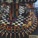
Step 10: Wheel Hill One: Part 1 (of 2)


The basic size for the wheel hill is:
Big wheel with it's small tyre.
Each wheel on a white (original color) rod, held together by a connector.
The distance between each pair of wheels is one blue rod.
I don't use the blue rings, only when the balls have problems getting trough all the time.
Step 11: Wheel Hill One: Part 2 (of 2)


Every few pair of wheels, there should be an overhead wheel to slow the balls down. Especially when you make the angle higher than the usual 45°.
The overhead wheels are at one yellow rod hight (90° on the hill's surface) and use the large wheels with large tyres. They can't move sideways (I use the small grey gears) but have to rotate without much friction.
When the balls have difficulties on passing underneath an overhead wheel, push the wheels aside with a blue ring at both sides.
The support for this hill can be made as you want but the line of wheels should be supported at enough points so it doesn't start to bend down and snap.
Step 12: Wheel Hill Two: Part 1 (of 2)


This wheel hill uses small weels. I don't think it's as good as the first wheel hill because the balls don't actually "roll" trough it. Also, it's shape and size is not easy to attach/implement in a structure.
Either way, here is the basic shape of the second wheel hill;
Step 13: Wheel Hill Two: Part 2 (of 2)


Also on this wheel hill, ball speeds might run high (depending on the angle). If they get too much speed and fall off, try adding a mill to slow it down.
Because I wanted to build it next to the first whee hill and didn't have enough k'nex to build another support beam, I loosely attached it to the first beam. The rods to attach it are shown in the second picture.
Step 14: Moving Stairs


This is a tricky path. I had first build the design and everything worked fine. As soon as i constructed it in the ball machine, things went wrong.
It'll be trial and error. Try to find what is the right counterweight for the stair to work. And the pusher doesn't always works as wanted either.
In these pictures the green connector "pusher" is positioned horizontally. But if the balls don't get enough "push" to make it all the way off the stair, try using it vertically.
Originally, the stair had these 2 long "teeth" that guided the ball to the next stair, but for some reason, the stair no longer wanted to stay in balance.
And here's another tip: try to make the ball land at the far end of the red connector. If it sits against the back side (grey connectors) of the "cup", it rathers falls off then rolls away.
Step 15: U Turn


This path is mainly a path with a small slope and curved flexible rods.
the length is in grey rods while the hight goes in blue/green rods. This is propably not a good combination if sizes are based on blue rods (horizontal/vertically). However, This should work on red rods aswell. Make sure the ball can get enough speed to overcome the resistance the yellow connectors give. Or build it solely out of the yellow (or orange) connectors.
The last image shows how one U turn goes and has the flexible rods for the next turn connected at one end. The process just repeats itself in both directions.
This u turn is used to create a zig-zagging path. But it can be used as a single element aswell.
Step 16: V Path


This path is most likely nothing 'new'. Though, it provides less friction to the passing balls then a normal 'rail' with connectors would.
The reason I do put this in the instructions is because the construction is a bit more complicated then a plain path and never had a good close-up view.
I also use this as a zig-zagging path. Though it may have plenty of other uses.
Step 17: V Path - Wheel Version


Yet another application for the small wheels. This path uses rather much pieces for just letting the ball pass by.
The wheels are put at the end of the green rods and easilly come off. So using this is a bad idea if there are eny shocks.
Either way, it's a good use of the "useless" wheels in ball machines.


