

Introduction: DC Motor Control Arduino Uno R3


In this experiment, we will learn how to control the direction and speed of a small-sized DC motor by a driver chip L293D. Making simple experiments, we will just make the motor rotate left and right, and accelerate or decelerate automatically.
Step 1: Components
Step 2: Principle
The maximum current of an Arduino I/O port is 20mA but the drive current of a motor is at least 70mA. Therefore, we cannot directly use the I/O port to drive the current; instead, we can use an L293D to drive the motor. L293D L293D is designed to provide bidirectional drive currents of up to 600mA at voltages from 4.5V to 36V. It's used to drive inductive loads such as relays, solenoids, DC and bipolar stepping motors, as well as other high-current/high-voltage loads in positive-supply applications.
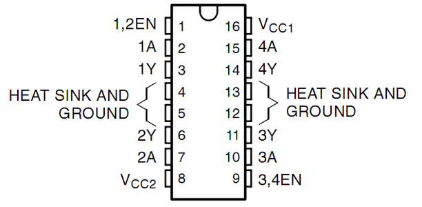
See the figure of pins below. L293D has two pins (Vcc1 and Vcc2) for power supply. Vcc2 is used to supply power for the motor, while Vcc1, for the chip. Since a small-sized DC motor is used here, connect both pins to +5V. If you use a higher power motor, you need to connect Vcc2 to an external power supply.
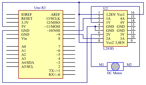
Step 3: The Schematic Diagram
Step 4: Procedures

The Enable pin 1,2EN of the L293D are connected to 5V already, so L293D is always in the working state. Connect pin 1A and 2A to pin 9 and 10 of the control board respectively. The two pins of the motor are connected to pin 1Y and 2Y respectively. When pin 10 is set as High level and pin 9 as Low, the motor will start to rotate towards one direction. When the pin 10 is Low and pin 9 is High, it rotates in the opposite direction.
Step 1:
Build the circuit.
Step 2:
Download the code from https://github.com/primerobotics/Arduino
Step 3:
Upload the sketch to the Arduino Uno board
Click the Upload icon to upload the code to the control board.
If "Done uploading" appears at
the bottom of the window, it means the sketch has been successfully uploaded.
Now, the blade of the DC motor will begin rotating left and right, in a speed that varies accordingly.
Step 5: Code

//DC Motor Control//The DC motor will begin rotating left and right, and its speed will vary accordingly.
//Email:info@primerobotics.in
//Website:www.primerobotics.in
/***************************************/
const int motorIn1 = 9; //attach to one of the pin of the motor
const int motorIn2 = 10; //attach to another pin of the motor
/***************************************/
void setup()
{
pinMode(motorIn1,OUTPUT); //initialize the motorIn1 pin as output
pinMode(motorIn2,OUTPUT); //initialize the motorIn2 pin as output
}
/****************************************/
void loop()
{
clockwise(200); //rotate clockwise
delay(1000); //wait for a second
counterclockwise(200); //rotate counterclockwise
delay(1000); //wait for a second
}
/****************************************
/The function to drive motor rotate clockwise
void clockwise(int Speed)
{
analogWrite(motorIn1,Speed); //set the speed of motor
analogWrite(motorIn2,0); //stop the motorIn2 pin of motor
}
//The function to drive motor rotate counterclockwise
void counterclockwise(int Speed)
{
analogWrite(motorIn1,0); //stop the motorIn1 pin of motor
analogWrite(motorIn2,Speed); //set the speed of motor
}
/****************************************/
Step 6:


