

Introduction: DIY 100 Watt Audio Amplifier


Hey! everyone My name is Steve.
Today I'm going to show you How to Make 100 Watt Portable Amplifier in a Very Simple Way
Let's Start
Step 1: Features

Output Power
- 100 Watt x 1 @ 4Ohms
Input Power
- 16 - 35V DC
Built-in Protection
- VERY HIGH OPERATING VOLTAGE RANGE (±40V)
- DMOS POWER STAGE HIGH OUTPUT POWER (UP TO 100W MUSIC POWER)
- MUTING/STAND-BY FUNCTIONS
- NO SWITCH ON/OFF NOISE
- NO BOUCHEROT CELLS
- VERY LOW DISTORTION
- VERY LOW NOISE
- SHORT CIRCUIT PROTECTION
- THERMAL SHUTDOWN
Step 2: Thing I've Used
LCSC
- TDA7294 - http://bit.ly/301mpBe
- 22K - http://bit.ly/2Uz77zQ
- 680R - http://bit.ly/2Uz77zQ
- 10K - http://bit.ly/2Uz77zQ
- 22uF 25V - http://bit.ly/2Uz77zQ
- 10uf 50V - http://bit.ly/2Uz77zQ
- 100nf 50V - http://bit.ly/2Uz77zQ
- 820uf 35V - http://bit.ly/2Uz77zQ
- XT30 - http://bit.ly/2Uz77zQ
Banggood
- 24V SMPS - https://bit.ly/2DXQ5Yq
- Soldering Iron - https://bit.ly/2DXQ5Yq
- Flexible Arms - https://bit.ly/2DXQ5Yq
Amazon
- 24V SMPS - https://amzn.to/2BvUejG
- Soldering Iron - https://amzn.to/2BvUejG
- Flexible Arms - https://amzn.to/2BvUejG
Aliexpress
- 24V SMPS - http://bit.ly/2Vva3P9
- Soldering Iron - http://bit.ly/2Vva3P9
- Flexible Arms - http://bit.ly/2Vva3P9
Step 3: Circuit Diagram

You can see the circuit diagram to make it easier
Step 4: TDA7294

DESCRIPTION ABOUT TDA7492
The TDA7294 is a monolithic integrated circuit in Multiwatt15 package, intended for use as audio class AB amplifier in Hi-Fi field applications (Home Stereo, self powered loudspeakers, Topclass TV). Thanks to the wide voltage range and to the high out current capability it is able to supply the highest power into both 4Ω and 8Ω loads even in presence of poor supply regulation, with high Supply Voltage Rejection. The built in muting function with turn on delay simplifies the remote operation avoiding switching on-off noises.
Step 5: Sponsor

Today's Article is Sponsored by lcsc.com
They are the Largest Electronics Components Supplier From China Ready to Ship within 4 Hours and they ship World Wide
Step 6: PCB Board Designing
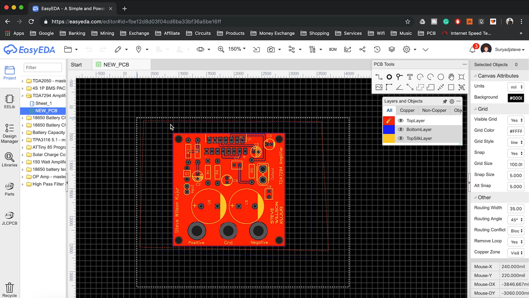
I Used EasyEDA To Create my PCB Using the Circuit Diagram Provided by STMicroelectronics and it took me about 2 Hours to Design
You can see I've used XT30 for Speaker output for easy plug and play
and for power input, I've used 3 Bullet connectors
You can Download the Gerber Files
Gerber & Circuit Diagram - http://bit.ly/2VnGGSU
Step 7: Ordering the PCB


Nowa Days it has been very easy to order PCBs and it doesn't cost you much, Yeah you easily do this in a Perf Board but the PCB Looks way better then Perf Board and Very Safe to Work So You can Put little work and money to get Professional Results
For This Project, I've used ALLPCB Service for Manufacturing my PCB and it took about 24 Hours to Manufacture my PCBs and within 7 Days they Delivered it to my door Steps
And the Quality is Just Amazing
Step 8: Soldering


I gathered all the components and soldered all the Resistances first, and then Soldered the Capacitors According to the Circuit Diagram and used a Cutter to cut all the extra legs
And then I've Soldered the Main Ic TDA7294
After That, I've Soldered the 3.5mm Bullet Connectors And XT30 Connector and it took me about 30 minutes
Step 9: Heat Dissipation


I've used a Decent Size Heat Shink for Heat Dissipation it is very necessary to use a Heat Shink Otherwise You'll burn the Chip
And it is very important to use a good quality thermal compound for better heat flow
I applied a little quantity fo thermal compound to TDA7294 IC and tighten it up with heatsink
Step 10: Stands Off


After the heatsink, I used 4 stands off to give it some clearance
Step 11: Power Supply


I used 2 SMPS each 24V @ 6 Amps giving a total of 48V @ 6 Amps
The SMPS is Connected in Series " It's Called Daul Power Supply "
+24 0 -24 V
You can also use a Transformer Based Power Supply no issues with that
Step 12: Setup and Enjoy


First I've connected the Speakers with XT30 Connector
Second I've connected the 3 Power Supply Cable via Bullet Connector
- Red - Positive
- Green - Ground
- Black - Negative
Third I've connected the Audio Input cable and connected it to an Audio source
You Just Made It
Thank you for visiting my Instructables Stay tuned for next Projects


