

Introduction: DIY Ambient Light Alarm


The idea ofthis project is to create an alarm that wakes via ambient light. In itself, this isn’t terribly hard. All you need is some LEDs, a clock and a microcontroller of some kind. Wire it all up, write some code and you’re done. I believe there are already numerous tutorials on how to do something like this. It’s been done many times before and honestly, isn’t very interesting. Thankfully, I decided to make this alarm as a birthday present for my girlfriend who despises anything tec. Apparently, wires are ugly and analog is the way to go. So here is the aim: take some LEDs, a clock and a microcontroller of some kind, wire it all up, write some code for it, and then hide it in a wooden shell to make it look nice and analog.
Inspiration for this project is the "DIY Heng Lamp" by JustAddSharks. I love the idea of using floating corks in the middle of a round lamp as a switch to turn the light on and off. This is a perfect concept on how to activate the alarm and how to turn it off again once I’m awake.
With the activation switch taken care off, the next step is to find some nice way to set the time at which I want to be woken. Moving away from the Heng Lamp, I decided to make the alarm circular and use two disks to set the hour and minute. This means that the ‘device’ will not actually be able to tell the current time. Considering that I’m building an alarm and not a clock, I think that’s okay.
So here is how the alarm works. Set the time at which you want to be woken using the hour and minute disk (similar to a real clock, the set hour and minute are at the top, at the twelve o’ clock location). Connect the two corks in the middle and to activate the alarm. The LED’s in the back will slowly start turning on 15 minutes before the set time. Once the time at which you want to be woken has been reached, the LED’s will have reached maximum brightness and a small piezo speaker will start making some noise. Disconnect the corks in the middle at any point to turn the alarm off.
As a small bonus, if no time has been set, connecting the corks turns the alarm into a lamp. I also included one button at the side of the base which can be used to control the brightness of the lamp and set the current time for when I don’t want to wire the microcontroller up to a PC. I have included instructions on how to use the alarm in the pictures.
The list of required parts is somewhat long, but manageable. I'm going to link the parts I bought, but most are from a German store
For the ‘structure’ and base:
- Lot’s of plywood. Mine was 4mm thick since that’s the only thing I could get for reasonable price locally. Both the base and the cork would profit from some ticker one
- 30 x 30cm opaque acryl (2mm thick) glass (mine is 70 percent opaque, see-through works too but doesn’t look as nice)
- Some metal balls to make the base heavier. I used 100 8mm iron balls
- Magnets, many magnets. Use whatever you can find. I had to learn the hard way that bigger actually is better. I used 8 x 8 x 4 mm and both 6 x 2mm and 4 x mm discs
- 20 bright LED modules. I used 10W, 30V white LEDs. These are super bright and the generated heat is manageable (when operated at 24V)
For the electronics on the inside:
- ATMega328P-PU
- DS13072 Real time clock module (RTC)
- Button Cell holder, 20mm, and a 3V Lithium button cell battery as a backup power supply for the RTC
- Piezo Buzzer
- Miniature push button
- Breadboard
- 100kR Resistor
- 2x 10kR Resistor
- 20x 200R Resistor for the LEDs
- 2x 22pF ceramic capacitor
- 470uF electrolytic resistor
- 330nF electrolytic resistor
- 2x 100nF ceramic capacitor
- 9x Reed contacts (get at least 10, these things are fragile)
- 16MHz standard quartz
- 32.768 kHz quartz
- Logic level N-Chan MOSFET (I used a IRLZ 34N)
- 2.1 DC socket
- DC Power-Supply (I used a 18W, 28V/0.64A one. Different voltage will of course mean that you will need different resistors for the LEDs)
- Voltage Regulator to convert the 28V to 5V (I used a MC 7805 CTG)
- Heatsink for the voltage regulator (I’m not positive that this is necessary but better safe than sorry. What I can say, the one I used is massive overkill, but it works so who am I to complain)
- Micro-Switch
And of course, some tools are needed, including
- Laser cutter
- Arduino board for programming the ATMega, I used an Uno clone
- Solder iron
- Wood glue
- Glue gun
- Sanding paper
- The usual tools require for basic electronics and woodworking
Step 1: Building Main Structure


The order of the next couple of steps doesn’t really matter too much. I started off with the LEDs since that was the only thing I had on hand. I would however recommend starting with building the main structure instead since it makes everything else easier.
Cut out the provided files out of the plywood. You should end up with 5 pieces out of wood and one out of acryl glass. You can go ahead and glue together the 3 LED parts seen in the picture. DO NOT GLUE THE OTHER PARTS TOGETHER JUST YET, you will not be able to insert the reed contacts later on if you do.
One important thing, I left a notch on the in- and outside to help with taking the minute and hour disk off once the alarm is finished. Make sure they are on the same side as in my picture.


Step 2: Taking Care of LEDs


With the main structure taken care off for now, you can shift your attention to the LEDs. As always, it pays to properly plan first before buying anything.
We are going to use 30 LED modules (DC-LE14154), all in parallel. Each can be operated with a maximum of 30V. However, operating them at such a high Voltage generates quite some heat and is a good bit too bright. The first time I connected them to a 30V power supply I couldn’t see anything for the next half hour. If you don’t know at which voltage you want to operate the LEDs, connect them to a variable power source and just look what suits you best. For me, that was 26V.
When using LEDs, you should always use a resistor in series. And yes, you will need a resistor for each LED, using one resistor for all the LEDs defeats the purpose. LEDs are current driven and need to be protected from overheating. With the LEDs that I used for this project, at least 1V should drop off at the resistor. Less is possible, but 1V or more is optimum. Since I’m using a 28V PS, I’m actually dropping 2V at the resistor, I simply couldn’t find a good 27V PS. Calculating the needed Resistors is simple. I want to drop 2V and measured a current of 10mA when using the LEDs at 26V. Hence, R=U/I, I need 200R resistors. If you use any parts that differ from mine, you will have to do the calculation yourself.
With the theory out of the way, you can begin building your LED ring. I started off by bending one side of the resistors by 90 degrees as can be seen in the first picture. The bent wire can then be pushed through the hole of a LED module. Solder the wire to the module and cut off excess wire. I soldered the resistors to the positive side of the LEDs. You can use the negative one instead, just make sure you use the same side for all LEDs.
Now is an appropriate time to test each LED. Connect them to your PS one at a time to make sure they work. Better now than later. Once that is done, begin with the cumbersome process of soldering the LED ring. Using the main structure build in the previous step helps with getting the spacing right. It’s better to use wire that is slightly too long. You can always bend it to decrease the distance between two modules. There is nothing that can be done about wire that is too short.
Once the LED ring is complete, solder one wire to the positive ring and one to the negative ring. These wires will later be used to power the LEDs. You can see my complete ring in the third picture where I tested the MOSFET (you don't have to do this. First time using a MOSFET so I was curious). Once your ring is done, glue them into the main structure build in the previous step. I found a generous amount of hot glue to work very well for this. If you want you can go ahead and attach the acryl glass now.
Step 3: The Step That Will Make You Want to Quit, Reed Contacts


This step is the step that sucked the most. Be very careful when working with the reed contacts, they are very sensitive and will break. When working with the Reed contacts, I found it best to lay the glass tube of the contacts on top of a magnet, that way they were always oriented in the best way for operation. Bend the wires by 90 degrees in such a way that the contacts fit well into your main structure build in step one and start soldering them together. You should get something like I did in picture one. Use the main structure to determine how long the wires need to be. You can connect the ground wires of all the reed contacts, that way you won't have 18 wires flying around later on.
Once that is complete, you can continue building the main structure. You should have two pieces of the structure, one with many small holes for magnets and slits for the reed contacts and one with cable channels. Place the reed contacts into the slits of the first piece, place the second piece with the channels on top and pull all the cables though the channels. Glue the two wood pieces together. As with the LED structure, make sure the notches are on the same side as shown in my picture.
Once the glue has dried, bend all the wires so they follow the channels and fixate them with some hot glue. For the last step, I found it best to hold the reed contacts in place with magnets that I placed over the slits (as seen in the second picture). This ensure that the contacts extend to the top of the slits and are in proper position before you fixate them.
It’s very hard to keep track of which wire belongs to which contact. I have included a picture that shows which contact should be connected to which pin of the ATMega. If you switch things up, you can always fix it in the software later on, but soldering them in the proper order makes things easier.
Once you are done with this step, congratulations are in order. You are finished with the worst of it.
Step 4: Building and Attaching the Corks


In this step, we will build the corks. Cut them out of plywood using the attached file. They consist of 6 disks each. Both have one disk with a very small hole, allowing the thread to pass through, and multiple disks with larger holes. These larger holes will build a chamber to hold the magnets. As you will probably have noticed, the chambers are different for each cork. This is due to me running out of magnets and using some larger ones for one cork. Make sure to plan how many magnets you need before ordering!
In the end, the different magnet sizes work in my advantage. It’s very beneficial to have multiple strong heavy magnets in one cork and smaller lighter one in the other. That way, you can have the heavier cork be the upper one and the lighter one the bottom one that will be pulled up by the stronger magnets. Whichever constellation of magnets you go for, make sure to adapt the laser file accordingly.
You will also notice that each cork has at least one disk with a medium sized hole. This hole will be used to attach the thread. I sadly did not take any pictures of this part, but the idea is to glue together a 'small-hole-disk' with a 'medium-hole disk' and to pull a thread through the small hole into the medium one. Make many knots, big enough to not be able to slide through the small hole anymore. Just for good measures, fill the medium hole with hot glue, this way the thread should never be able to slide out.
Finish assembling the corks as seen in my pictures. Make sure the magnets are oriented in such a way for the corks to attract each other. You should end up with two attracting corks, each one with a thread hanging out through a small hole.
With the corks complete, it’s time to attach them to the main structure. I left a notch for the top cork in the piece with the cable channels from the previous step. Tie a bunch of knots and hot glue the thread into position as seen in picture five. You will have to play a bit with the length of the thread. The top cork should go about half way of the frame (see the last picture). The bottom cork will need to be attached to the micro switch. Solder the cables to the switch and tie the thread to the lever. You can see this in the third picture. The length of the thread needs to be so, that the bottom cork cannot touch the top cork but is still attracted enough to float in the air and activate the switch. Once satisfied, hot glue micro switch into position. Make sure the thread and lever can still move freely, otherwise the switch will not activate.
Once done, you can glue the base structure containing the reed contacts together with the structure containing the LEDs. Make sure the notches allign.
Step 5: Building the Base


With the main structure complete, it is time to build the base and the weights used to make the alarm more stable. The weights container is straight forward. Glue everything but the lid together, insert iron balls and then attach the lid.
The laser file for the weights container also includes four smaller parts. These will be used to attach the button and the PS socket to the base of the alarm (I have included pictures of this in the next step). The hole sizes are exactly what is needed to attach the button and socket I used. When using different parts, the laser files might need to be adapted. Using generous amounts of wood glue, you should be able to attach these parts to the PS socket and the button as can be seen in picture five.
Building a fully closed base is simple, as has been demonstrated with the DIY Heng Lamp. However, the problem with this design is that the electronics inside will become inaccessible. With the software probably needing a patch down the line and the backup battery a replacement, that simply wasn’t acceptable. For this reason, I designed the bottom layer of the base to act as a ‘sliding door’, it can be removed if the need should arise.
The rest of the parts have to be glued together as shown in my pictures. The holes for the button and power socket can be placed wherever you want, just make sure it doesn’t conflict with the weights. Don’t attach the lid of the base just yet, it will make soldering much easier.
Attachments


Step 6: Soldering


Time to heat up the iron and start soldering. Not really much to say here, you’ll just have to follow the wiring diagram. The blue connects are wires that will be connected to the Arduino during programming. I used female jumper cables for this. When connecting the reed contacts, micro switch and LEDs, remember to pull the wires though the lid of the base.
When you are satisfied with your work, you can go ahead and close everything up. Glue the button and power socket into the holes left in the base, put all your electronics into the base, glue the lid onto the base and then the main structure to the base.
-------Theory behind wiring diagram-----
This part is only for those who are interested. The diagram works, but here is what the theory is behind the design.
The heart of the whole device is the ATMega328. This is the microcontroller that is included in most Arduinos, making writing code for it super easy. I chose to use an ATMega instead of a full Arduino because, 1) it’s smaller and 2) it’s cheaper. The ATMega328 cannot function on its own and will need a 16MHz standard quartz and two 22pF capacitors. If you look closely, you should be able to find these parts on your Arduino board.
The time is provided by a real-time clock module, a DS13072. Once set, it will keep track of the time as long as it has power. This last bit is the reason for the backup battery. The clock will keep going, even when the alarm does not have power. The battery will only kick in when the main power source is off, and should last over 10 years (or so the manufacturer claims). The SCL and SDA pins need to be pulled up, which is being done with two 10kOhm resistors.
The LED modules are great due to being super bright and not very hot. The only drawback is, they need a supply current of 28V while the ATMega and DS13072 only need 5V. This leaves us with two options, a) use a 5V power supply and step up to 28V for the LEDs, or b) use a 28V power supply and step down for the ATMega. As it turns out, option a) will require a power supply which can supply some rather high currents, which is harder to find than a proper 28V one.
We will control the brightness of the LEDs via PWM. For this purpose, I used a IRLZ34N, a logic driven N-Channel MOSFET. The MOSFET will make the LEDs appear less bright by flickering them at a very high frequency, supplied by the ATMega. When connecting the IRLZ34N you need to make sure to connect it to a digital pin capable of PWM such as the PD3 pin.
Step 7: Das Ziffernblatt, the Disks


Last physical step: laser out the disks. I glued some paper over the numbers to make them look nicer, which also helps with hiding the magnets that would otherwise be visible through some of the numbers. Once satisfied, glue the disks containing the numbers together with the disks that will hold the magnets. I have included a sketch that show which number should align with which magnet. This is the way I did it, if you do it differently, that’s okay, you will have to change some things around in the software though. However you decide to glue the disks together, just make sure the magnets align with some number.
Speaking of magnets, it’s time to insert them into the disks and, if you haven’t already done so, into the main structure. When inserting the magnets, make sure the magnets of the main structure attract the magnets of the disks.
And that’s it, you are done with building the alarm. If you want, and I would recommend you to do this, you can sand down the edges and apply some wax to the surfaces to make everything smooth and nice to the touch. You might also need to sand down the inside of the hour disk and the outside of the minute disk. This makes it easier to turn them.
Attachments

Step 8: Software


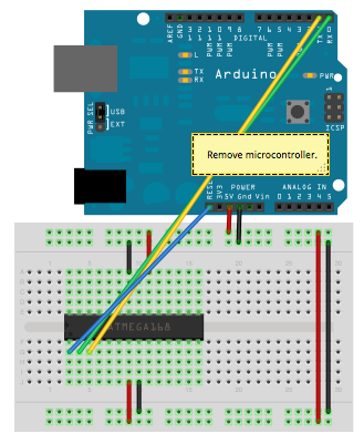
Time for the Software. Connect the ATMega to your PC as seen here. Remember to remove the microcontroller from your Arduino. I have included my Arduino sketch but you can make your own if you want. I have set everything up the way I find it the most intuitive but there is no reason anyone has to do it the same way as me. I'm sorry if the code is confusing, it's the first time I have programmed anything longer than 10 lines.
One thing everyone will have to do is figure out which reed contact combination belongs to which number. If you look at the design, there are 4 reed contacts to figure out which hour has been set, and 5 for the minutes. For me, hour 5 has no contact registering a magnet, while some other hour has all contacts sensing a magnet. To help figure out which number corresponds to which contact combination, I have written up a short Arduino Sketch 'GetHourMinute.ino'. This code will tell you which contacts sense a magnet over the Serial Monitor. You will have to use the disks and write down each contact combination for each hour and minute. If you set everything up the same way as me, you should be getting the same combinations as me, but it's better to check.
If you look at the
beginning of my code (‘LightAlarm.ino’), you will see me initializing integer arrays like this:
int twelve[4] = {1,1,0,1};

int one[4] = {1,0,1,0};

int twenty_z[5] = {0,0,0,1,1};

int twenty_f[5] = {0,0,1,1,1};
You can see, e.g. hour twelve has the combination 1101, minute twenty 00011, minute twenty-five 00111… In the minute name, z means zero and f five, so ten_z corresponds to 10, ten_f to 15 and so on. The formatting of the combinations is as follows: hour={Reed1 ,Reed2, Reed3, Reed4} and minute={Reed5, Reed6, Reed7, Reed8, Reed9}. If you connected your reed contacts to different pins than me, make sure to adjust the code for this. The very first variables being declared are the pins for each contact, e.g. int Reed1 =2;, int Reed2 =4;…. Notice that these numbers are the Arduino function pins, not the actual pin number of the ATMega. I have included the pinmapping of the ATMega above (168 and 328 have the same mapping).
Once you know the combinations for each hour and minute, write them into the array like I did (if you glued the disks like me and soldered the contacts in the same order, you should have the same combinations as me). For my version of the alarm, some of the minute magnets do not properly align with some of the reed contacts. Because of this, I have multiple contact combination for the same minute setting. Since there are more than 12 possible combinations with 5 contacts, it is possible to assign more than one combination to each minute setting, increasing accuracy. You can see an example of this here:
int ten_f[5] = {1,0,0,0,1};

int ten_f2[5] = {1,0,0,1,1};

int ten_f3[5] = {0,0,0,1,1};
This means that I have three different combinations for 15 minutes. If you do end up removing some of my combinations or adding more, you will have to add/remove an array for each combination, and then go to the bottom of my code where you will find two functions, GetMinute() and GetHour(). There you will find lines like this:
if (memcmp( (const void
*)zero_f, (const void*)SetMinute, sizeof(SetMinute)) == 0){
 i = 5;
  }
The first line compares the current state of the minute contacts and compares it with the combination I defined as 5 minutes (zero_f). The second line returns a 5 if these two arrays match. If you added a new combination, you will have to add two lines like this for your new combination, resulting in something like:
if (memcmp( (const void
*)zero_f, (const void*)SetMinute, sizeof(SetMinute)) == 0){
i = 5;
if (memcmp( (const void
*)zero_f,2 (const void*)SetMinute, sizeof(SetMinute)) == 0){
i = 5;
}
Once you have updated all the combinations and made sure the pin assignments for all contacts, buttons, leds and the speaker are correct, your alarm should be fully functional, congratulations.
To set the time for the first time, set the current time with the dials, make sure the switch is not activated, and press the button for a brief time. The LEDs should flash once signaling that you have set the time. If you also want to set the date, I have attached a file by eGizmo that will do just that.
I will change to software around a bit more the next couple of weeks. Whenever I change something, I will post a changelog here.
Update 28.05.17, Version 2
- Pressing the button while the alarm is active (time set and corks connected) will turn on the LEDs. Pressing the button again will decrease the brightness until they are off. This helps with using the Alarm as a lamp
- LEDs will remain on while the melody is playing
- Disconnecting the corks while melody is playing will now interrupt the melody
- Disconnecting the corks while LEDs are blinking to tell the time will now stop the blinking
- Small changes to how a button press is registered to make changing brightness easier
- Some other small changes that are mainly aimed at increasing quality of the code but don't actually change any functions

Step 9: Some Customization

SOUND
I found the speaker to be too loud and rather unpleasant. To dampen it, I taped a sponge to the top of the speaker, making the sound much nicer but also a lot quieter. If you don't need a super loud alarm to wake you up, I would advice doing this.
Currently, the Alarm plays a rather long Melody:
int melody[] = {                                                                       // notes in the melody
  NOTE_D4, NOTE_G4,NOTE_FS4, NOTE_G4, NOTE_A4, NOTE_E4, NOTE_A4, NOTE_G4, NOTE_FS4, NOTE_E4, NOTE_FS4, NOTE_G4, 0,
  NOTE_D4, NOTE_G4,NOTE_FS4, NOTE_G4, NOTE_A4, NOTE_E4, NOTE_A4, NOTE_G4, NOTE_FS4, NOTE_E4, NOTE_FS4, NOTE_G4,0,
  NOTE_B4, NOTE_B4, NOTE_B4, NOTE_B4, 0,  NOTE_B4, NOTE_B4, NOTE_B4,0, NOTE_B4, NOTE_A4, NOTE_G4, NOTE_A4, NOTE_B4,0,
  NOTE_B4,NOTE_B4, NOTE_C4, NOTE_B4, NOTE_A4, NOTE_E4, NOTE_A4, NOTE_G4, NOTE_FS4, NOTE_E4, NOTE_FS4, NOTE_G4
};

int noteDurations[] = {                                                               //// note durations: 4 = quarter note, 8 = eighth note, etc.:
  4, 4, 4, 4, 4, 4, 2, 4, 4, 4, 4, 2, 2,
  4, 4, 4, 4, 4, 4, 2, 4, 4, 4, 4, 2,2,
  2, 2, 4, 2,4,  2, 4, 2,4, 4, 4, 4, 4, 2,2,
  4, 4, 4, 4, 4, 4, 2, 4, 4, 4, 4, 2
};
I found the speaker to be
too loud and rather unpleasant. To dampen it, I taped a sponge to the top of the speaker, making the sound much nicer but also a lot quieter. If you don't need a super loud alarm to wake you up, I would advice doing this.
Currently, the Alarm plays a rather long Melody:
The first array holds the notes to be played, the second the duration of each note. For the notes, we need pitches.h by Tom Igoe from the Arduino Example Codes. If you want the alarm to play a different melody, simply change these two arrays. You will also have to do a small change in the PlayMelody() function:
void PlayMelody(){
    for (int thisNote = 0; thisNote < 53; thisNote++) {                                    // iterate over the notes of the melody:.
    int noteDuration = 1000 / noteDurations[thisNote];
    tone(speaker, melody[thisNote], noteDuration);
    int pauseBetweenNotes = noteDuration * 1.30;
    delay(pauseBetweenNotes);
    noTone(8);
}
}
Replace 'thisNote < 53' with whichever number of notes you have
LIGHT WAKING
Currently, the light turns on 15 minutes before the set time, increases the brightness slowly for the first 5 minutes and then faster to full for the last 10. If you want to change any of that, you only need to do some small changes.
int WakeTime = 15; //How many minutes before alarm to start turning on the light
This number gives the total wake time in minutes.
const long first_interval = 10000;                                                 //Length of first interval steps in ms
const long first_interval_steps = 30;                                              //number of interval steps for slow beginning, SET IT HERE
The first constant is the duration of the steps of slowly turning on the light in milliseconds (each step corresponds to increasing the brightness by 1 out of 255 total). The second constant gives the number of steps of slowly turning on the light. 30*10000ms=300000ms= 5min. The step duration of the remaining steps afterwards will automatically be calculated. Changing either constant will change the slow waking time. I found this to be necessary due to the LEDs turning too bright too fast, probably because our eyes see light on a logarithmic scale and not linear.

Participated in the
Lights Contest 2017

Participated in the
Power Supply Contest


