

Introduction: DIY Arduino Capacitive DDR Pad

This guide describes how to build a capacitive dance pad for dance games like StepMania. There are no mechanical parts involved as the pad is capacitive and the construction requires no tools whatsoever. You cannot use the pad with shoes and you cannot trigger more than two arrows at once. The materials used are easy to acquire and are pretty cheap (25$ if you don't have anything already on the following list). I had most already so I only had to pay only 5$.
How a capacitive sensor works
Only one side of the insulator is coated with conductive material. A small voltage is applied to this layer, resulting in an electrostatic field. When a conductor, such as a human finger (or feet in our case), touches the uncoated surface, a capacitor is dynamically formed. The sensors controller (in our case an arduino) can then detect whether a capacitor is formed or not, thus can detect whether we touch the panel or not. It is most often used in simple applications such as industrial controls and interactive kiosks, but we are going to use it for a dance pad.
Step 1: Materials

- Arduino
I used an arduino uno clone, but you could use about any (working) arduino you want, clones or not. Be sure to check if the pins that are used are on your arduino and you're all set.
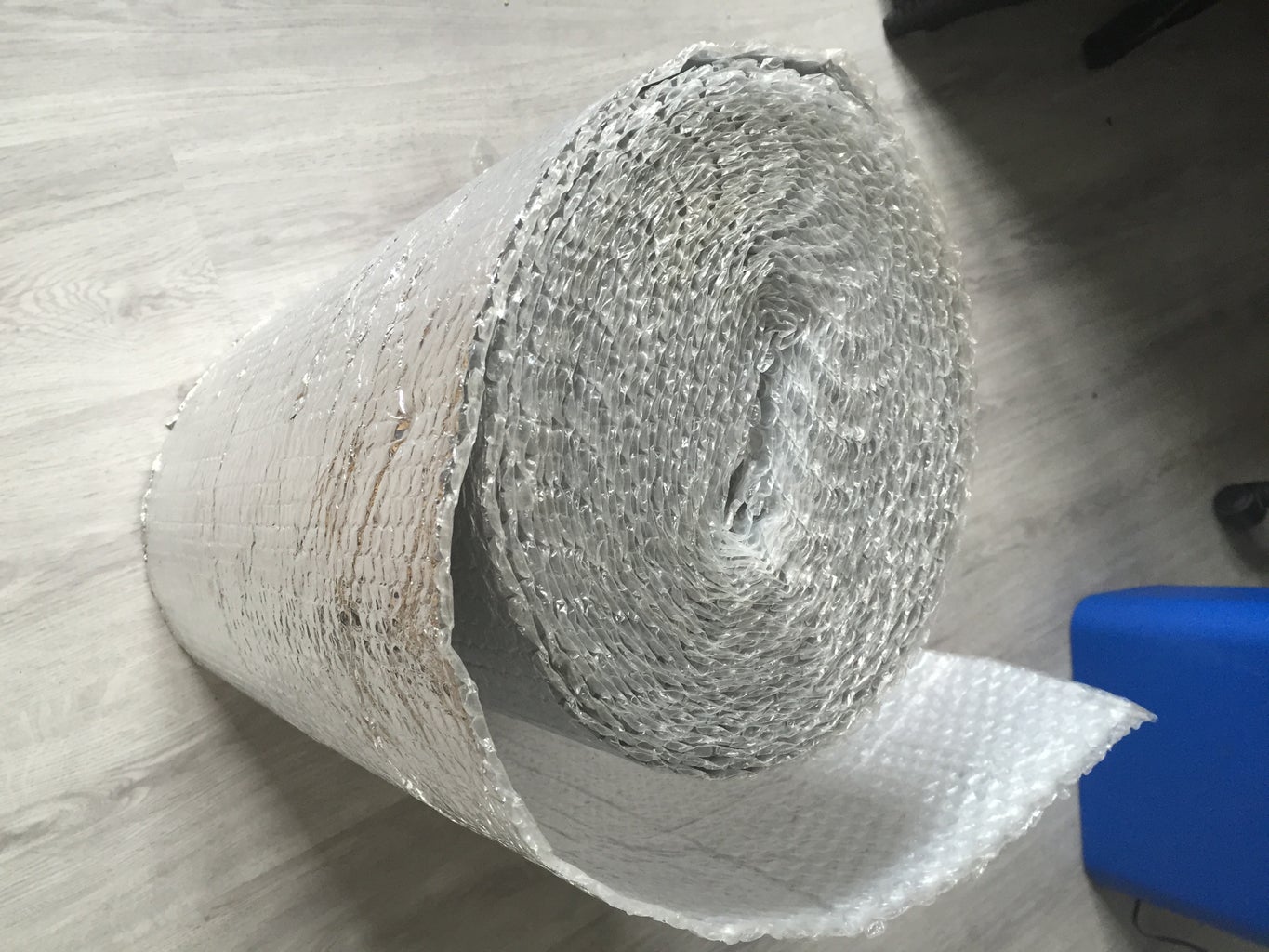
- Conductive panels
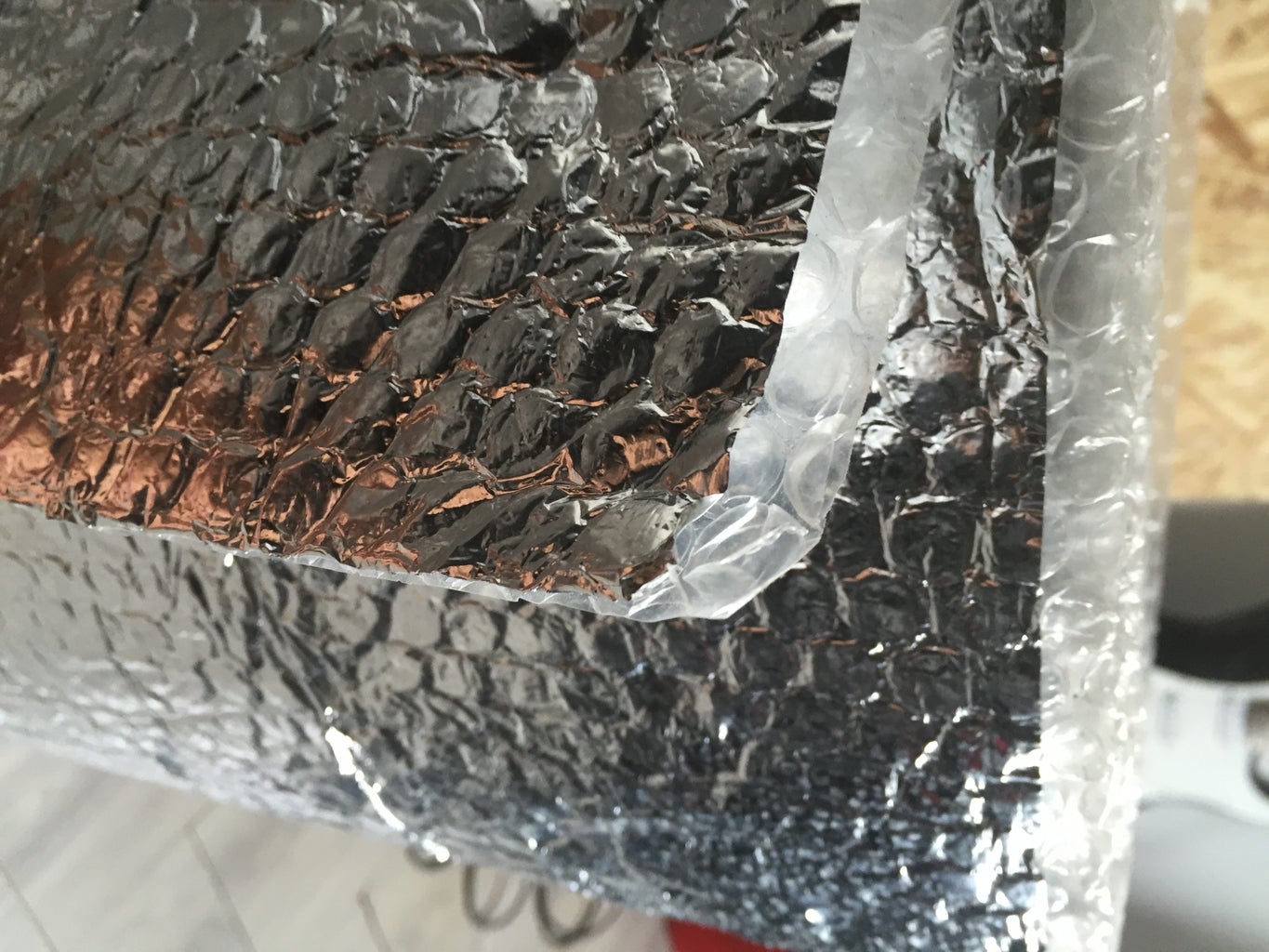
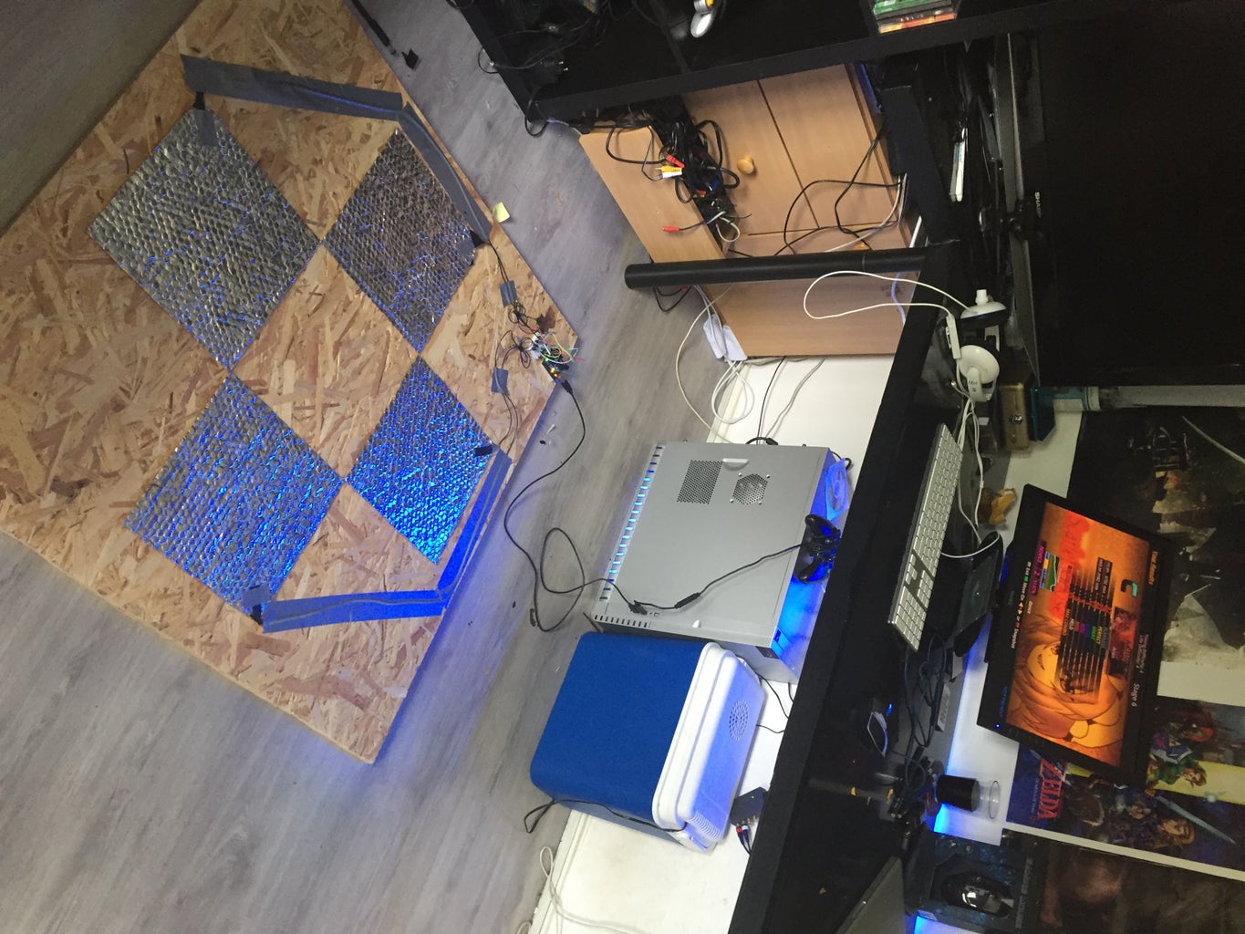
These are the surfaces you will be stepping on. Each arrow should be about 28x28 cm / 11"x11". I used aluminum isolation material (basically aluminum foil with bubble wrap pasted onto it) but you can use any conductive metal you want. Just aluminum foil works but will tear apart pretty easily, you can cover the aliminum with a protective layer but the layer should be very slim otherwise the pad will not work.
- Resistors
330, 4.7k, 5.6k & 6.8k ohms
You'll probably only need four for the final circuit, but since a resistor costs 2 cents, you're better off buying at least 10 of each. The wattage/material is not important.
- Solderless breadboard
These things are great for testing purposes. A tiny one with about 200 points is enough and should cost no more than 3$
- Jumper cables (Male/Male)
Good things to have with your arduino, used for the breadboard. Get about 20 of them because you may need to do some cable stripping later on
- Panel (100x100cm) (optional)
I used a cheap wooden panel of about 100x100cm to put the pads on. This is optional of course and you don't have to get this if you want to make your pad stationary
- Double sided tape (optional)
Optional but highly recommended if you want to make your pad durable. Used to apply the arrows onto your floor or panel.
- Copper wire (5m)
- Wire stripper or a knife
- Duct tape
- Electrical tape
Step 2: Making the Arrows Ready for Use
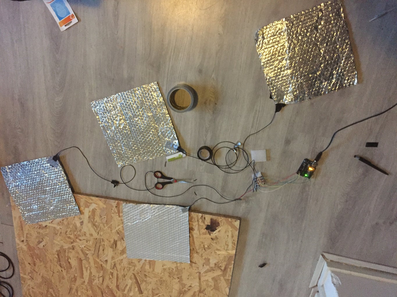
Cut your arrow panels to 28x28cm if you haven't done that yet and place the arrows into the position you'd like. Don't paste them onto the wooden panel or floor just yet. Take one corner as your arduino/breadboard corner and cut the into 4 wires which each roughly fits each panel to the corner. Take both ends of one wire and strip them with either a wire stripper, a knife, or scissors, with about 3cm stripped on each side. Repeat the process for the other 3 wires.
Once the cables are all stripped begin by attaching one side of a wire to one arrow with electrical tape. Then do some normal duct tape over the electrical tape so that it stays in place. Once again repeat the process for the other 3 arrows. Be sure that the copper wire is touching the aluminum foil and that you mask all of the bare copper.
Now use double sided tape (or duct tape) to tape all the arrows into position.
Once everything is in position, get 2 jumper cables and cut them somewhere in the middle (you can also use 4 jumper cables if they are really short and cut them at the end)
Now strip those cutted jumper cables to about 2 or 3 cm. If done right you should have 4 stripped jumper cables with only copper wire at the end.
Twist connect the 4 stripped jumper cables to the 4 copper wires attached to the arrow panels. You should now have 4 arrow panels in place with cables leading to a male jumper, be sure to mask the bare copper wire off with electrical tape.
If you want to, now is the time to tape down the wires with duct tape to avoid tripping over them
Step 3: Arduino and the Breadboard
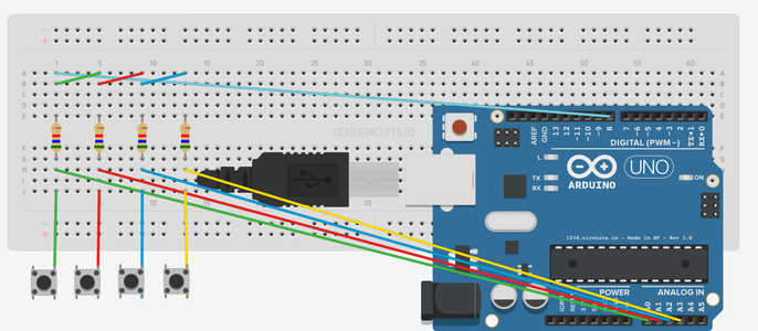

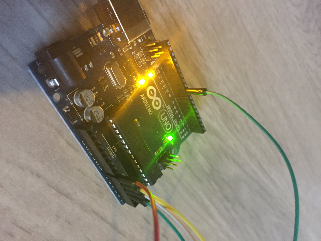
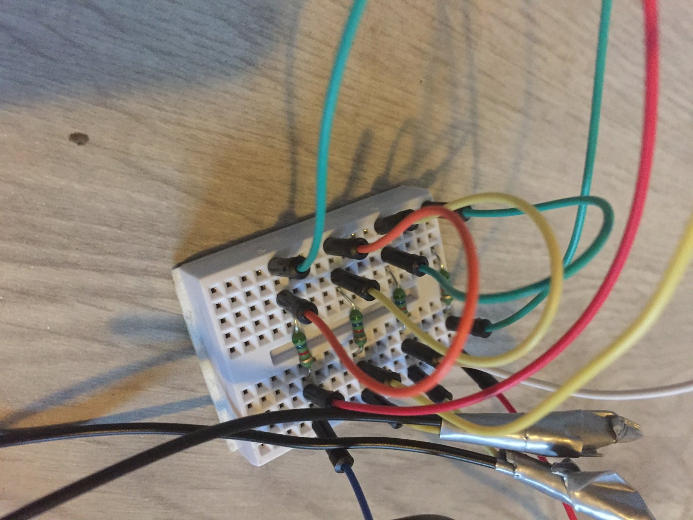
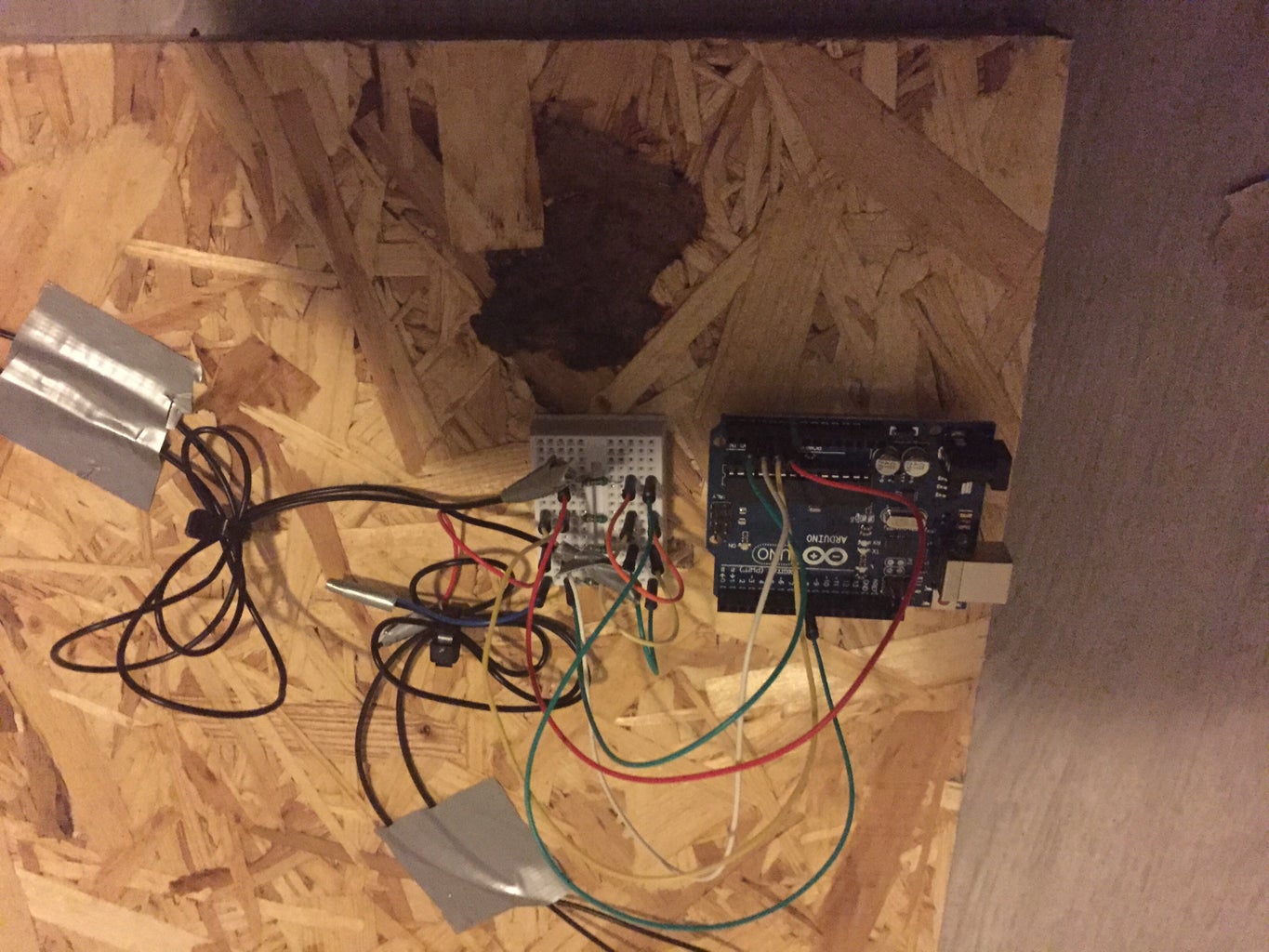
Connect everything together using the above schematic. See the buttons as arrow pads and connect these with your new pad to jumper connection. Try the 5.6k resistors first as these are the ones that usually do the trick.
Download the file below, extract them and place the folder somewhere you won't lose it.
Now it's time to flash your arduino. You'll need the Arduino IDE for this, which can be found online at arduino.cc.
Copy the "CapacitiveSensor" folder to the "libraries" folder found in Arduino's install directory. Once it's in place, you should be able to compile and upload ddr_serial.ino to your board. Note the name of your Arduino's serial port (should be something like COM4); you'll need this later.
Once it's been uploaded, open the Serial Monitor. If everything works properly, you should see the following string printed hundreds of times a second:
"0;0;0;0"
When you step on an arrow, one of the four values should jump from 0 to 30. If it doesn't change, either the resistance is too low, or the arrow connection is faulty. If the arrows are always stuck on 30, the resistance is too high. If stepping on two arrows causes both of them to jump from 30 to 0, the resistance is slightly too low. The exact resistance required will vary depending on the material and size of the arrow pads, but should be in the ballpark of 5000 to 7000 ohms per arrow, with the same resistance on each arrow.
The only way to find the right resistance for your specific arrows is to experiment with different resistors. The arrows themselves add their own resistance; how much resistance they provide depends on the material and amount of metal involved, and will affect how much resistance you'll need on the breadboard. Keep in mind that resistors can be connected in serial: If you put a 330ohm resistor in front of a 5.6kohm one, the total resistance will be the sum of the two (5930 ohms). This way, you can fine-tune the value by combining a large resistor with a small one.
If any of the values are above 1000, the circuit is not closed, which likely means you've made a mistake somewhere in the wiring. The Arduino can sometimes freeze when experimenting in the Serial Monitor; simply unplugging it and plugging it back in will solve this.
Once you've found a resistance that works, you should be able to step on two arrows at a time and see two values jump up in the serial monitor. If that does not work try getting a higher resistance. At this point, all that's left to do is install the driver.
Included is a simple application called DDR_ArduinoFeeder. It takes the output sent by the Arduino, and uses it to trigger button presses in a virtual joystick driver called vJoy. The source code is included for anyone who's curious how it works.
Install vJoy, and launch Configure vJoy. Make sure device 1 exists, and that it has at least four buttons. Once this is done, launch DDR_ArduinoFeeder, enter the name of your Arduino's serial port (should be something like COM4; see the Arduino IDE), and click on Connect. As long as the feeder application is running, you will be able to use the pad as a standard controller. You only need to enter the serial port once; on subsequent launches, it connects automatically.
Attachments

Step 4: Enjoy
Make sure your ArduinoFeeder is opened and launch your favourite ddr software, like stepmania or osu!mania.
Go to the controls screen and configure your dance pad.
Once you've done that you should be able to enjoy your self built dance pad!
Huge thanks to Loginer for creating the ArduinoFeeder software and the schematics.


