

Introduction: DIY Arduino Geiger Counter


Hello everybody! How do you do? This is project How-ToDo my name is Konstantin, and today I want to show you how i made this Geiger counter. I started to build this device almost from the beginning of last year. Since then it has gone through 3 complete rework and my laziness. The idea to make a dosimeter appeared from the very beginning of my passion of electronics, the topic of radiation was always interesting to me.
Step 1: Theory


So actually dosimeter is very simple device, we need the sensing element, in our case - the Geiger tube, power for it, usually it is about 400V DC and an indicator, in the simplest way is just a speaker. When ionizing radiation striking the wall of Geiger counter and knocked out electrons from it, it makes the gas in the tube conductive, so power goes directly to the speaker and it clicks, you can much better explanation on the web if interested. I think everyone will agree that clicks are not the most informative indicator, although it will be able to warn about the increasing radiation, but counting them with a stopwatch for an accurate results is kind of weird, so I decided to add display some brains.
Step 2: Design


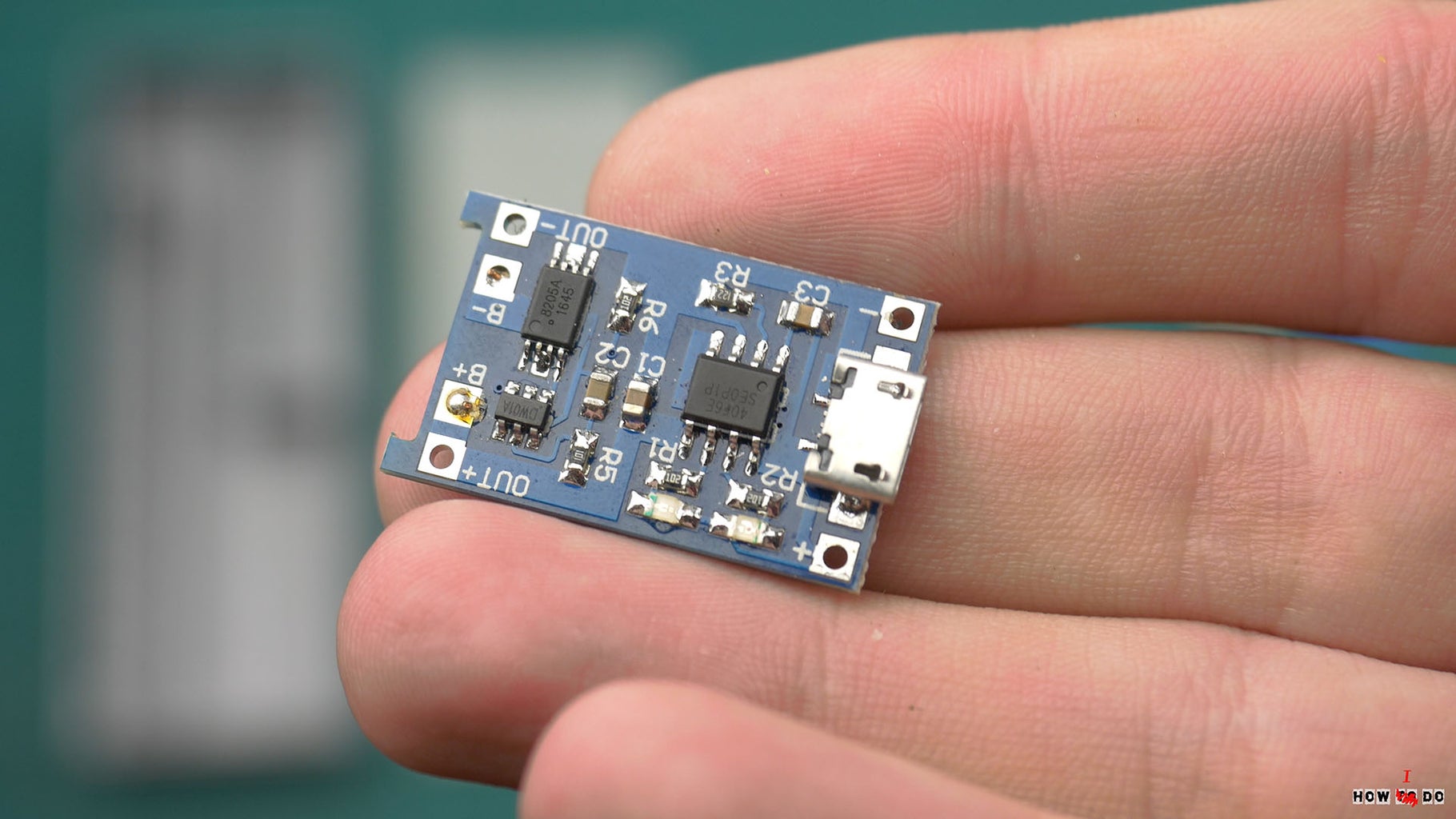
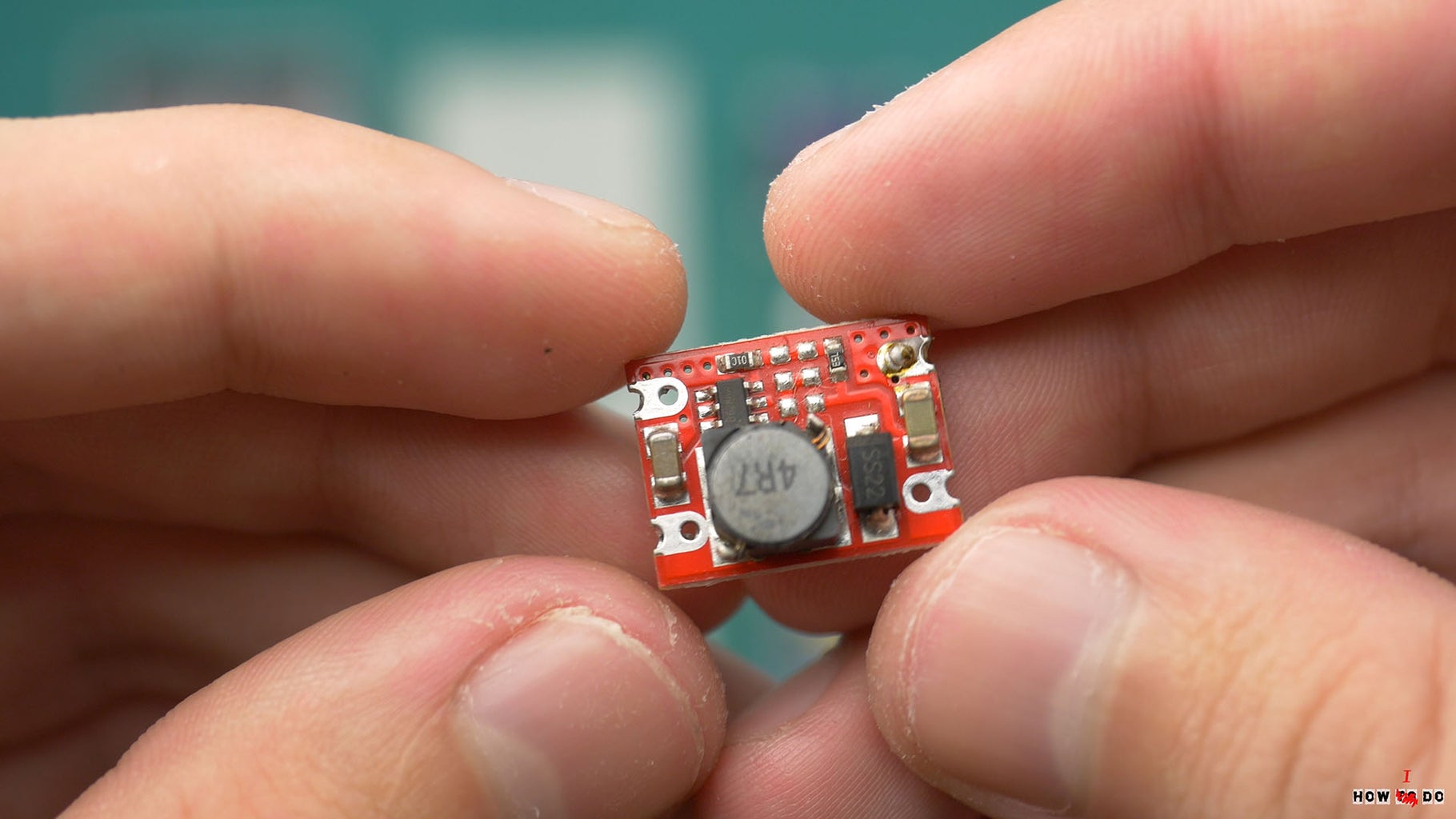
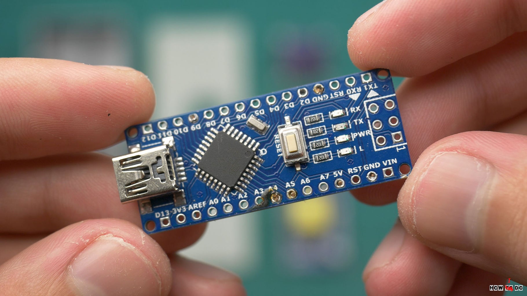
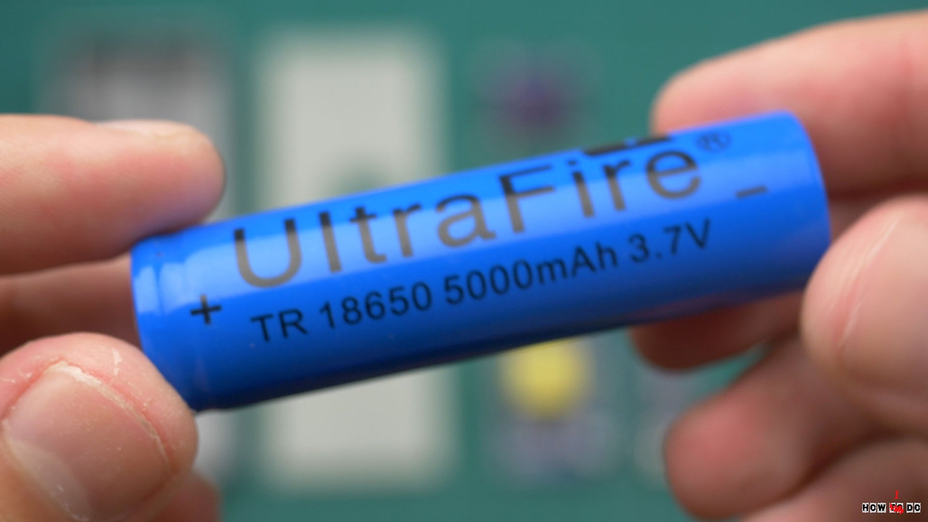
Lets move to the practice, for the brain I choose arduino nano, program is very simple it's counting pulse of the tube for a certain time and display it on LCD, also it's show nice radiation warning sing and battery level. As a power source I use 18650 battery, but arduino needs 5v, so I DC-DC bust converter and li-ion charger to make devise completely autonomous.
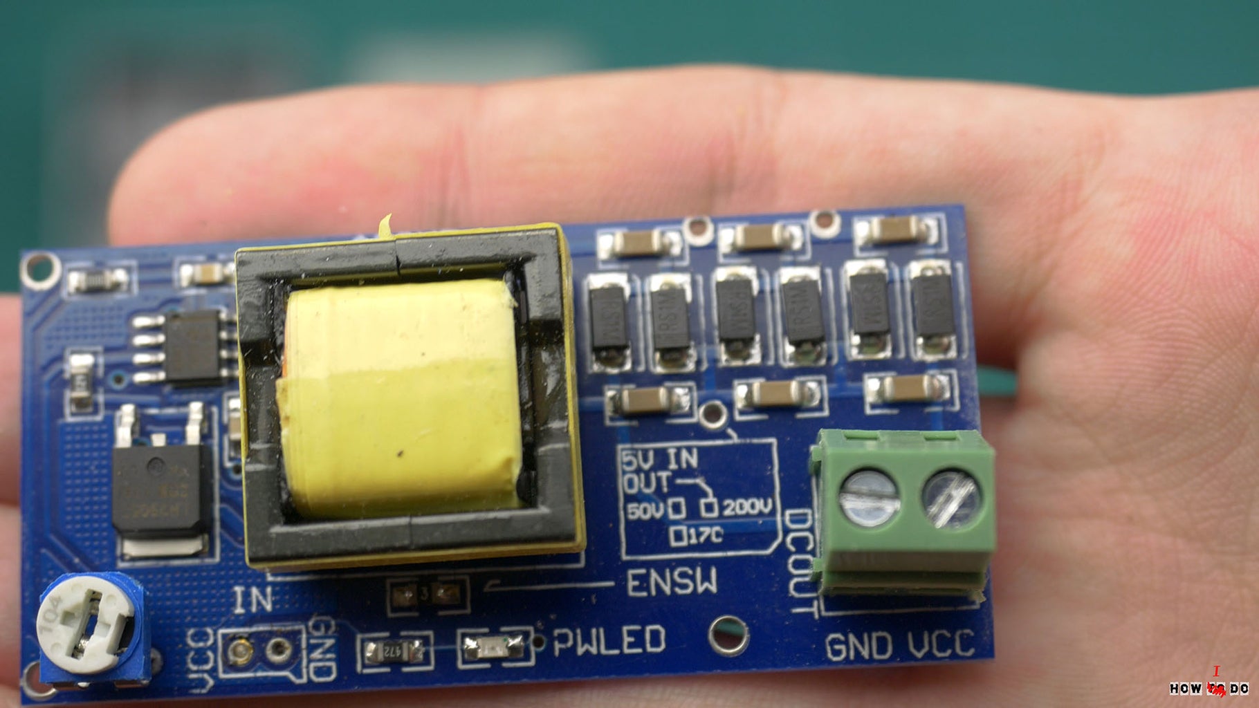
Step 3: High Voltage DC-DC


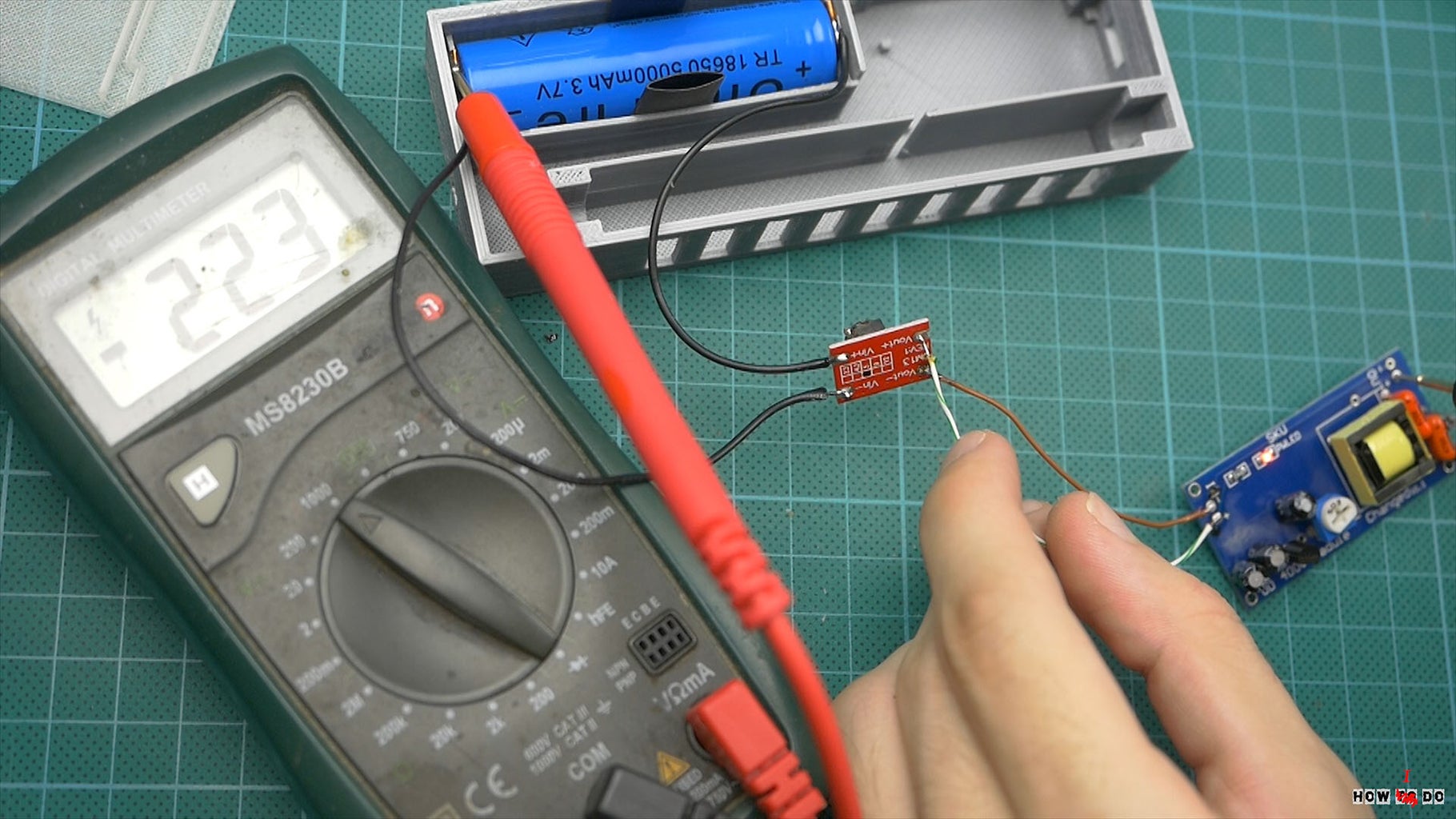
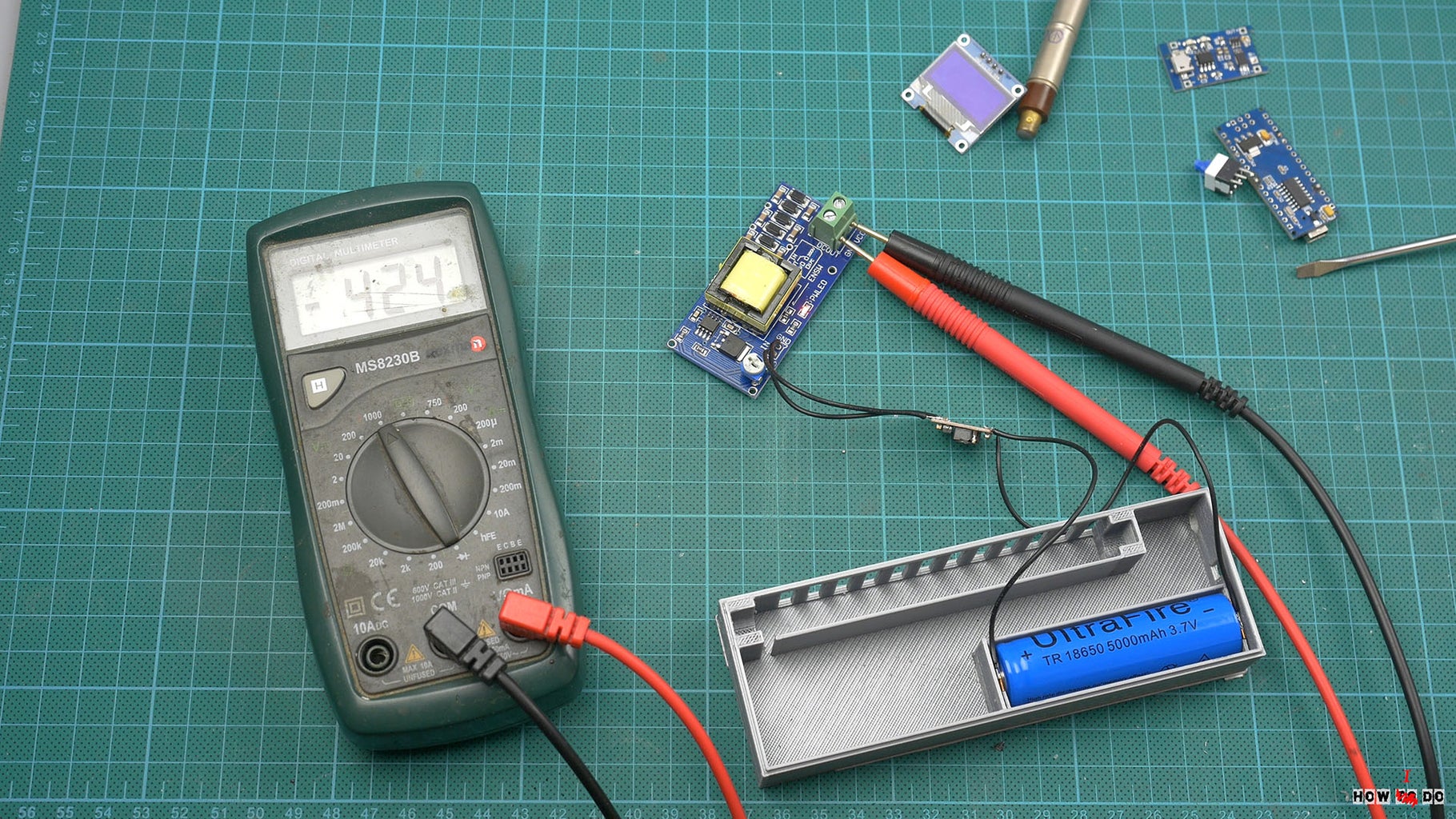
I have hard time working on a high voltage power supply, originally I build it by myself, wound a transformer about 600 turns in secondary coil , drive it with MOSFET transistor and PWM from arduino. It's working, but I want to keep things simple, it's better when u can just buy 5 modules, solder 10 wires and get working devise then winding a coil, adjusting PWM, I want anyone to be able to repeat it. So I found high voltage DC-DC bust converter, it's strange but it's hard to find and most popular module has about 100 sales. I ordered it, made a new case, but when start to test - it gives out a maximum of 300V but the description says up to 620v, I tried to fix it, but the problem probably was in transformer. Whatever, I bought another module and it came in different size description says the same... I returned money but keep this module because it gives 400v we need, but anyway maximum 450 instead 1200 (something is really wrong with Chinese measuring devises... ) I made a new case, again.
Step 4: Components


And so in the end we have a design almost entirely consisting of modules:
- High voltage step up DC-DC ( Aliexpress OR Amazon )
- Charger ( Aliexpress OR Amazon )
- 5v DC-DC bust converter ( Aliexpress OR Amazon )
- Arduino nano ( Aliexpress OR Amazon )
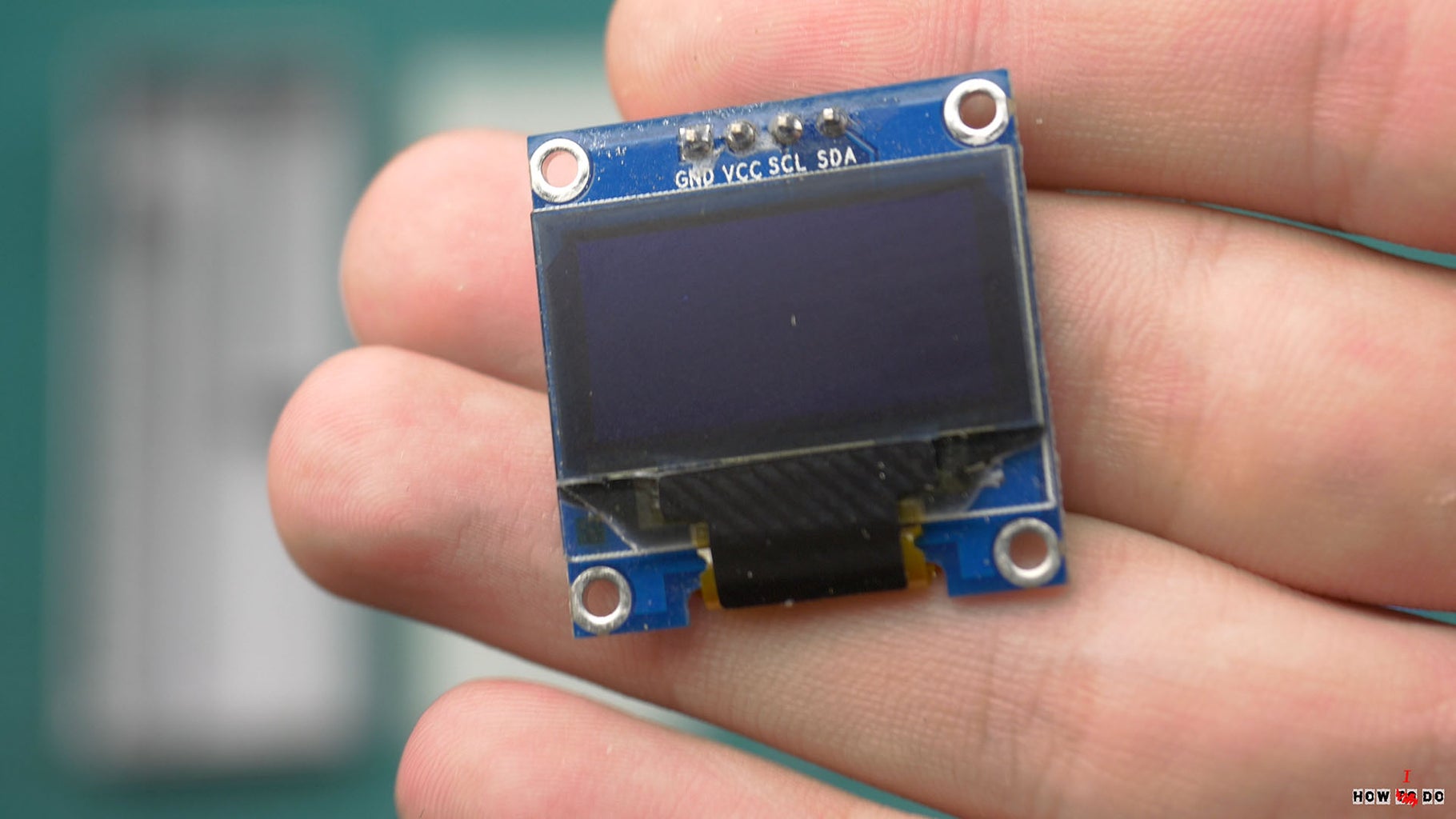
- OLED display there is 128*64 but in final I'm using 128*32 ( Aliexpress OR Amazon )
- Also we need transistor 2n3904 ( Aliexpress OR Amazon )
- Resistors 10M and 10K ( Aliexpress OR Amazon )
- Capacitor 470pf ( Aliexpress OR Amazon )
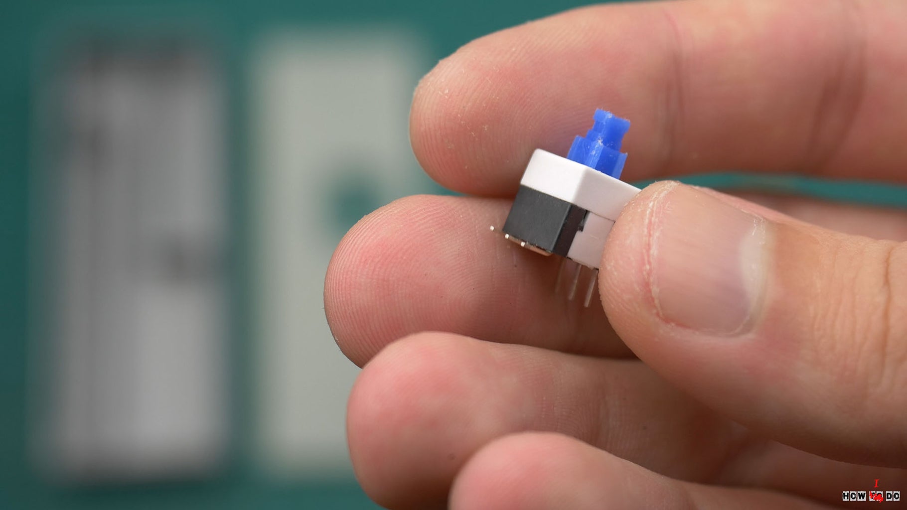
- Switch button ( Aliexpress OR Amazon )
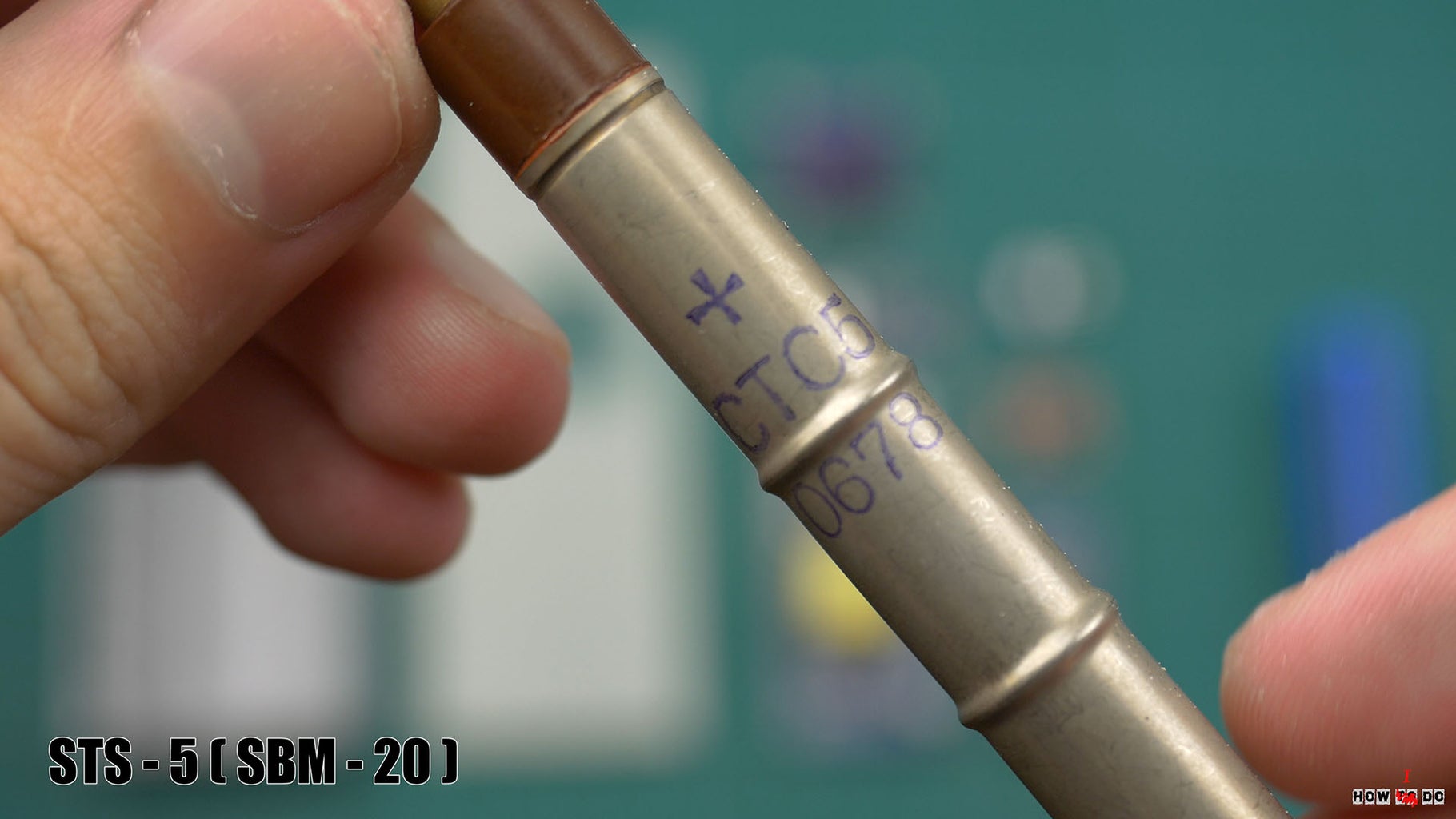
Battery, optional active piezo buzzer and Geiger counter itself, I'm using old made in USSR tube, called STS-5 it's pretty cheap and easy to find on ebay or amazon, also it's going to work with a SBM-20 tube or any other, you just need to write parameters to a program, in my case the value of micro-roentgen per hour is equal to the number of tube pulse in 60 second. And well, the case printed on a 3d printer .
Also there are pretty cheap Geiger Counter Kits u might be interested. ( Aliexpress OR Amazon )Step 5: Assembly

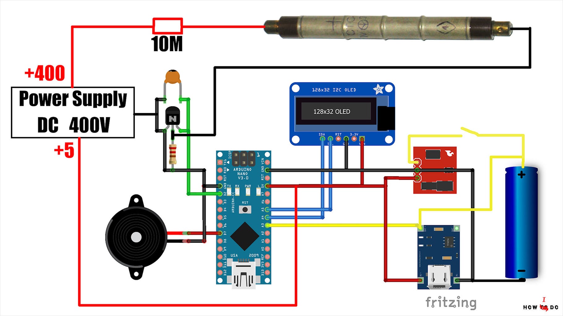
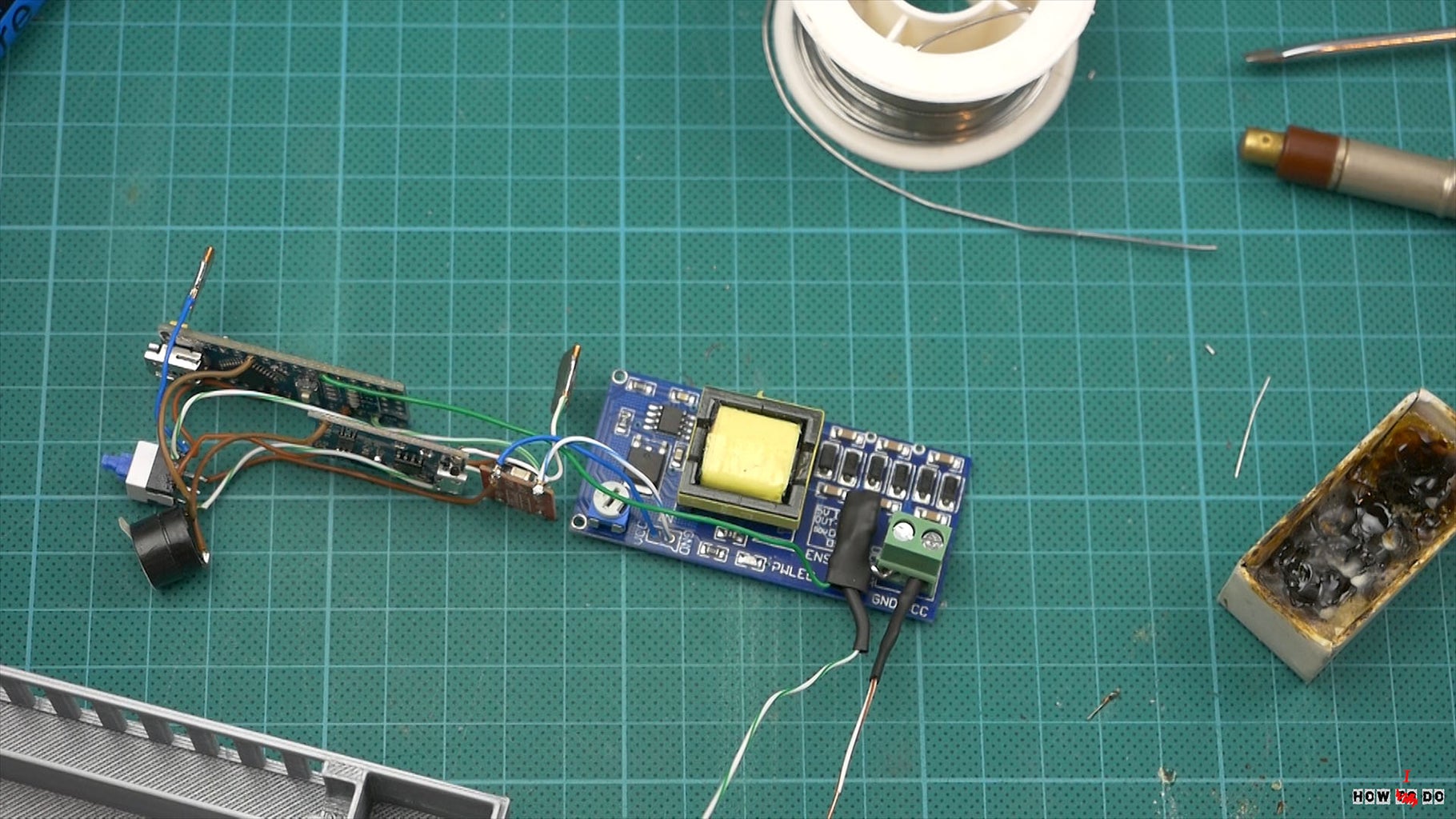
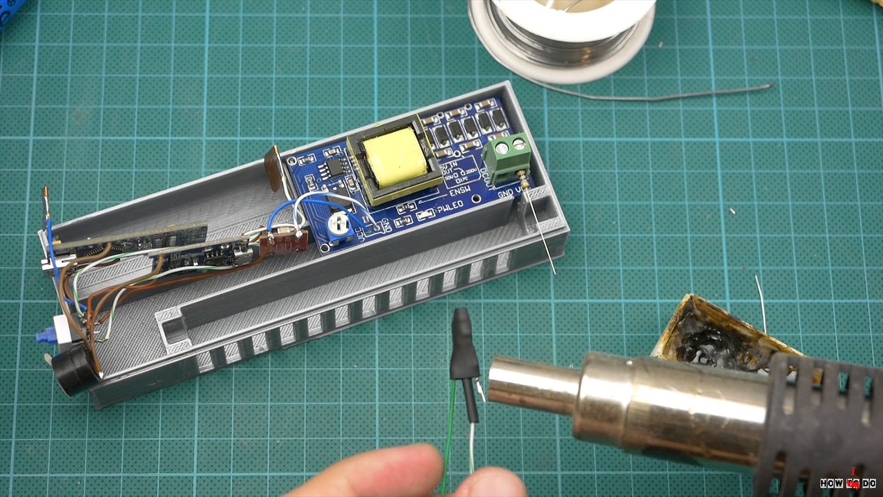

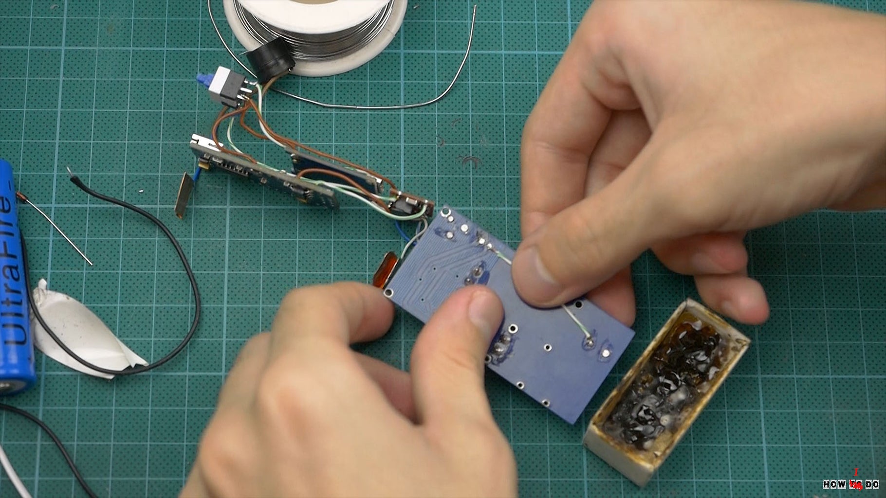

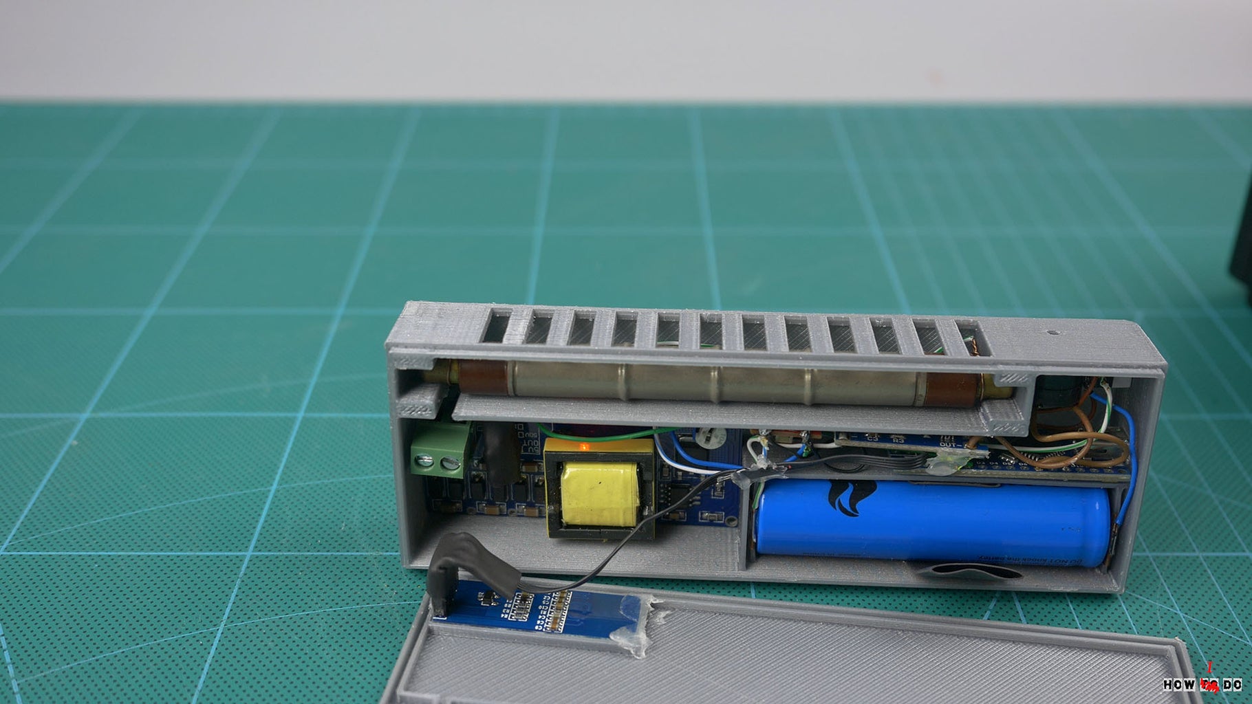
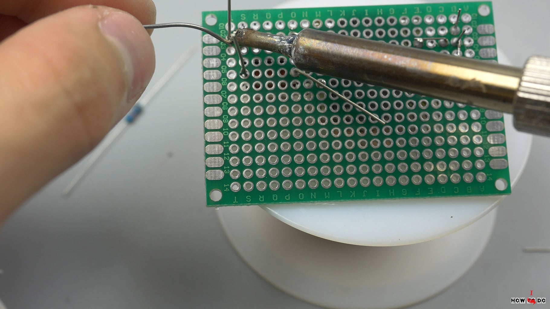
Lets start an assembly, the first thing to do is to set the voltage on the high voltage DC-DC with this potentiometer, for STS-5 it is approximately 410V. Then simply solder all the modules together by this circuit, I use solid wires, it will increase stability of construction and it is possible to assemble the device on the table, and then just insert it into the case. An important point, we need to connect in and out minus of the high voltage converter, I simply solder a jumper. Since we can't just connect an arduino to the 400v, we need a simple transistor circuit, I make it point-to-point wiring and wrapped it in a heat shrink tube, a 10MΩ resistor from + 400V was fixed right into the connector. It's better to make a cupper foil bracket for the tube, but I just twist a wire around, it's working fine, don't reverse plus and minus of Geiger counter. I connect display to the detachable cable, insulate it carefully, it's very near to the high voltage module. Some hot glue. And assembly is done!
Step 6: Final

Put it in the case and we are to test it. But I don't anything for tests, by the way Background radiation is looks fine. What can I say, is this devise working? Yes, sure. But I see a lots of way to upgrade it, for example large display so u can draw graphics, Bluetooth module, or use Sievert instead of Roentgen. I'm okay with device, but if u will upgrade it, please share! So thats all I got for today, hope u like it, and if u do please share this video in social media, it's really helps. Thanks for watching, see u next time!
Find me on social media:
https://www.youtube.com/c/HowToDoEng
https://www.instagram.com/konsta.kogan/

Second Prize in the
Arduino Contest 2017


