

Introduction: DIY Arduino: a Perfboard and 3 Simple Steps...


Hey there,
Ever wanted to build your own Arduino? Well, here’s how….
PS: For all those fanatics who’ve been pestering me ever since I built my first Arduino.
Inventory
- ATmega8/168/328 (Bootloaded)
- 28 pin IC Socket
- IC 7805T (+5v Regulator)
- IC LM1117T (+3.3v Regulator)
- 16Mhz Crystal Oscillator
- 10µF Radial Capacitor (x2)
- 10µF Tantalum Capacitor (x2)
- 22pF Ceramic Capacitor (x2)
- 0.1µF Ceramic Capacitor
- 220Ω Resistor (x2)
- 10kΩ Resistor
- Momentary Pushbutton
- Female Wall Wart Power Jack (DC barrel connector)
- Red and Green LEDs
Adapted from
Step 1: Setting Up the Power Supply


a. Place the Power jack at any of the four corners. The pin at the back which connects to the barrel, is the positive, whereas the pin at the bottom is the negative terminal. The additional pin at the side allows the application to detect whether a power supply is plugged into the barrel jack or not, thus allowing the device to bypass batteries and save battery life when running on external power; here, it may be left floating or shorted to the ground.
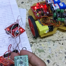
b. With the printed side facing you and the pins pointing down, connect the left leg (pin 1) of the +5v Regulator (IC 7805T) to the positive terminal of the DC Jack and the centre pin (pin 2) to ground. The IC requires two decoupling capacitors. Connect one 10µF radial capacitor between the input (pin 1) and ground, and the other 10µF radial capacitor between the +5v output (pin 3) and ground. Mind the polarity of the capacitors.
c. Similarly, with the printed side facing you and the pins pointing down, connect the right leg (pin 3) of the +3.3v Regulator (IC LM1117T) to the positive terminal of the DC Jack and the left leg (pin 1) to ground. The IC requires two decoupling capacitors. Connect one 10µF tantalum capacitor between the input (pin 3) and ground, and the other 10µF tantalum capacitor between the +3.3v output (pin 2) and ground. Mind the polarity of the capacitors.
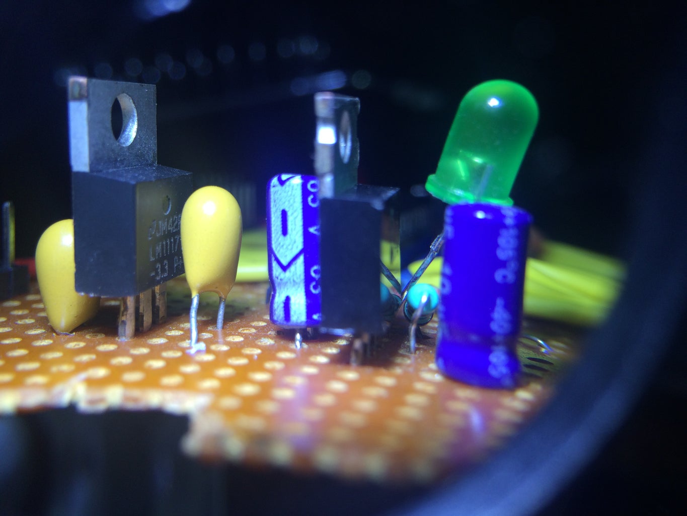
d. Add the power indicator LED to the circuit. Connect the LED anode (longer leg) to the +5v regulated output via a 220Ω resistor. Connect the LED cathode (shorter leg) to ground.
Step 2: Installing the ATmega IC


a. Solder the IC socket at a suitable place. Do not plug in the IC yet.
b. Connect pins 7, 20 and 21 to +5v output, and pins 8 and 22 to ground.
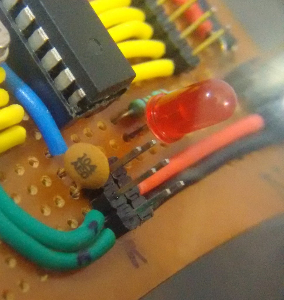
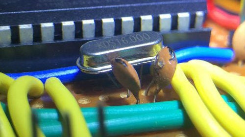
c. Add a 16Mhz crystal oscillator between pins 9 and 10. Connect a 22pF ceramic capacitor between each of these pins and ground.
d. Place the reset switch near the head of the IC socket. Connect the bottom-left leg to pin 1 on the IC (socket) and the top-left leg to ground. Add a 10kΩ pull-down resistor running from pin 1 to ground.
e. Connect the anode (longer leg) of the second LED to digital pin 13 (pin 19 on the microcontroller). Connect the cathode (shorter leg) to ground via a 220Ω resistor.
f. Solder the ISCP headers. Draw connections from +5v, Gnd, Rx (pin 2), Tx (pin 3) and RST (pin 1, via a 0.1µF ceramic capacitor).
Step 3: Uploading Sketches


a. Plug in the ATmega IC into the socket. Mind the notch!
b. Now, you will need a USB-to-Serial device. The FTDI FT232 basic breakout board serves the purpose. Simply run wires from the TTL header to the corresponding pins on the chip. Be sure that the pins are routed correctly as shown in the table.
c. Select the appropriate serial port, compile your sketch and hit upload.
In case the running sketch is not automatically interrupted to initiate upload, press the Reset button on the board just after the software reports that it is done compiling (when you see the message about the size of the sketch). It may take a few attempts to get the timing right between the end of the compilation and pressing the Reset button.


