

Introduction: DIY Autonomous Line Tracking With Obstacle Avoiding Robot (Rover)


WARNING : MAKE YOUR COMPUTER BRIGHTNESS LOW , BECAUSE THIS PROJECT EMITS A HIGH LEVEL OF AWESOMENESS THAT CAN HARM YOUR EYES :D 3:)
This project participated in RoboCup 2015 Egypt Local Competition and won "Best Design Award" with my team Abdelrahman Alaa , Ahmad Hisham , Hany Hamed with 2nd place too!!
If you ever though that line tracking bots (rovers) was a hard thing or a dream for someone who totally don't know what light sensor means ?! , If you always wanted to make a simple robot that track any black line you draw as it follows you for kind of project or as a start for entering competitions world !
your dreams and wishes in my Instructable will probably come true !
In the upcoming steps you'll learn how to make exactly the same tracking and obstacle avoiding robot with a couple of hours of your precious time to make it move..
Sorry, all Wiring will be made by professional software within 1 or 2 days so keep watching ....
Step 1: Materials and Tools We Need (Used) :

Materials :
- Arduino UNO
- Robot Chassis Kit ( In upcoming hours I'll add a lasercut file for a perfect chase , but any chassis design will be fine)
- Spacers : 6 short ones + 6 long ones.(More is better) (They should probably included with the robot kit)
- 2X geared motor
- 2X wheels (Mine was coated with silicon because we had a ramp in the competition field ,so it really help in going up)
- Omni wheel .
- Dual H-bridge board (Prefer L298)
- Power source : 7.4v Rechargeable Battery.
- Small Breadboard (to save in chassis space because my design was relatively small compared by others)
- Maximum 120x Jumper wires (Male-Male)
- UltraSonic sensor : (http://goo.gl/u8upXc)
- IR Sensor used as a light sensor : (http://www.cytron.com.my/p-lss05) (Best for smooth line tracking)
- Some mechano parts from old toy you have or maybe you could replace them with another thing (use your home stuff and imagination :D )
- Double face tape
Tools :
- Solder Iron (Optional ,but i use it in my chassis to expand some holes in my design :D )
- Cross Screwdriver.
- Screws with their nuts.
Step 2: Fixing Motors Place :


As you see in these two pictures I have used some of the chassis parts to fix the motors to the chassis .
First by using the brown parts (labeled in previous picture) one outside the chassis and one inside one of chassis holes , then putting the two motors between these two parts and put a long screw to move throw all parts , then lock on them with the nuts ... I really prefer to put nuts inside between the gap of the 2 motors as shown in picture, once the're fixed to the chassis by considering that there's a wheel that need to be attached to the robot so you need to make the motors almost on edge to avoid wheels friction with the chassis you'r able to move to next step. :)
Step 3: Front and Back Wheels Adding :


Back wheels adding is super easy you will just add them to there places with the pre-fixed motors...the main work will be in the front wheel after gathering all parts :
First : add a long nail with 4 nuts or more maybe ..depends on symmetry 2 left 2 right or 6 or 8 , add between the two first nuts the 90 Angle part (shown in pictures) .
Second : add 2 screws between the blue and red parts as shown in picture as tight as possible and let's call them the extend part ( because we have used them to extend Omni wheel to front of the robot away from the IR sensor)
Third : connect the extend part with the Omni wheel part as shown in pictures.
Fourth : connect the part made in third step to the main chassis and bring wires to the bottom of the chassis also shown in pictures.
Step 4: Fixing the IR Sensor :


PRECAUTION : Spacer length is relative to the optimum distance read for the sensor for the best value .
Use spacers to fix the sensor to the chassis ( you can check the optimum distance from the technical information file that you can find in the link for the sensor ) also get all wires to the bottom of the chassis.
Step 5: Fixing the H-Bridge and the Arduino With Wiring :


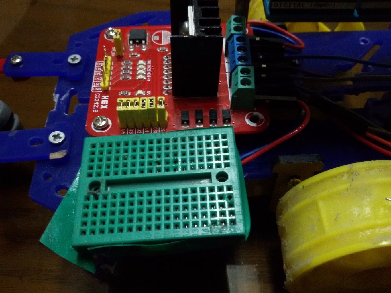


Here I used a small spacers because there was no space to put it with out spacers within my chassis dimension , then connecting the motor wires to the H-Bridge (wiring will be available soon) then adding the 5V and GND wires and lock on them by turning the screw on them .
I have added long spacers again for the Arduino due to the insufficient space in my robot chassis then wired all the scattered wires from all other sensors and stuff and also used the small breadboard to be an easy power disturbing board .
Step 6: Adding a Power Switch and Finishing Up :


Add a small switch to connected to the main power source to be a full cutting system button that stick to the chassis by double face tape, then add long spacers (based on the competition we have done this to make the height of the ultrasonic suitable for the mission)
On further explanation for how I made the sensor with servo junction from this project : (http://goo.gl/e63wwv) ... and it should be like shown in pictures .
Step 7: Arduino Coding :

Download Latest Arduino IDE from (arduino.cc)
then connect the Arduino by cable to the computer , open the file attached with this step then click Ctrl + U or click on upload button once your sketch is uploaded put the robot on the black line you wish him to track and enjoy the show ;)
now your expert line tracking man :D
please support us by making a one ;)


