

Introduction: DIY IR Proximity AKA Distance Sensor!!


The IR proximity sensor works on the principle
of optics in electronics. The sensor works by the application of voltage to the pair of LED’s (Light Emitting Diode) which in turns reflect the light. When the object is closer to the LED, the reflected light will be the stronger and when the object is far from the LED the magnitude of the reflected and intensity will be low.
These IR sensors can be used in obstacle sensing, color detection, fire detection, line sensing etc. The sensing and active element in the IR proximity sensor is a photo diode, so when object takes closer to the sensor the IR rays reflects and falls on the photo diode. Let’s make our project and understand the beautiful concept behind it.
Step 1: Components
1. IR Photo Diode pair (1) get it
from here https://www.utsource.net/category/sensors/other-sensor
2. 220 ohm (2) resistors and 10k ohm (1) resistor https://www.utsource.net/category/passive-components/resistors
3. Potentiometer 10k (1) https://www.utsource.net/category/passive-components/resistors
4. LM 358 IC https://www.utsource.net/category/elec-component/ic-chips
5. Bread board https://www.utsource.net/category/accessories-tools/breadboard
6. Power supply (3-12)V https://www.utsource.net/category/accessories-tools/battery-case
7. LED (1) https://www.utsource.net/category/led-lighting/led-modules
Connecting wires (as required) https://www.utsource.net/category/accessories-tools/wires-cables
Step 2: Principle
The active sensing component in the circuit is IR photo diode, so when more amount of incident light falls on the photo diode, the more will be the current flowing through it. So when any object is approaching or get closer to the diode sensor, the voltage across the photo diode increases and when no object is near the IR proximity sensor the LED is turned OFF. So basically more the closeness to the object more is the reflection and circuit LED turned ON. This sensor has a various types of applications in detection and sensing fields, so what are you waiting for let’s make it.
Step 3: Build the Circuit


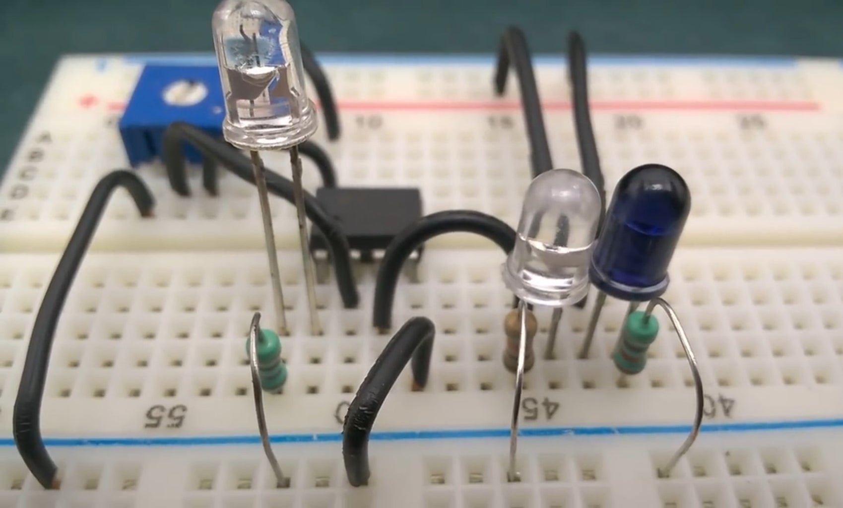

Procedure:
1. Insert the sensor Photo diode on the bread board (energy from IR radiation of Photo diode by PN junction is converted to electrical energy). And connect the cathode to the positive rail.
2. Now connect the positive terminal of the diode to the negative rail of the bread board via 10k resistor.
3. Place an IR LED on the bread board and connect positive terminal to the positive rail.
4. And negative terminal to the negative rail via 270ohm resistor.
5. Now insert LM 358 IC on the bread board.
6. Connect PIN 4 of IC to the negative rail of the bread board.
7. And PIN 8 to the positive rail of the bread board.
8. Place potentiometer on the bread board and connect the extreme terminals to the positive rail of the bread board.
connect the extreme terminals as shown below to the rails of the bread board.
9. Now connect PIN 2 of LM 358 to the potentiometer and PIN 3 to IR photo diode.
10. So finally placed the LED with positive terminal connected to PIN of LM358
and negative terminal to the ground via 220ohm resistor.
11. Connect the power supply to the respective rails of the bread board.
You can power the source using hobby 3.7v batteries.
Step 4: Now Test It!


Now when we are taking any object closer to the IR sensor the LED turned ON.
and when we are remove any object away from the sensor the LED turned OFF.
So this is the basic principle and explanatory procedure of IR proximity sensor working and its applications.
Utsource helped me with making this post, I recommend their site as their website is pretty amazing with tons of components for your projects.
If you need other IC chips, IGBT, Transistor and so on, please visit UTSOURCE.net
Thank You. Happy Making!!


