

Introduction: DIY Portable Camera Slider


In this instructable I am going to show you how to make a Portable Camera Slider using commonly available hardware.
This is a great DIY project for anybody out there who is willing to make a professional camera slider to take cinematic shots.
This camera slider is a great tool for any body related to photography so have a look at this video in which I am going to show you how to built one for yourself under 10$.
For more fun and useful projects don't forget to subscribe to my youtube channel for regular DIY project videos.
Regards.
DIY King
Step 1: Cutting the Wood


First off we have started with cutting some old classic pieces of wood and then started cutting them to get some finished blocks of wood to start building the frame of our Camera slider.
Using a miter saw, we have cut down square blocks measuring 3 inches each side and having a thickness of approx 20mm.
Three of these block are cut down and then the edges are finalised on a table saw.
Step 2: Side Blocks


The side blocks are made out of the wooden block that we have made in the previous step. Two of these blocks are made which act as standoffs for the camera slider and hold the sliding mechanism as well as it act as a holder for the sliding rails.
Initially the blocks are cut down to the following dimensions:
- Length: 3 inch
- Width: 4 inch
- Thickness: 0.8 inch
Then using a 3 inch diameter hole saw a circular cut is made at the bottom of both these wooden blocks to give it a nice shape. Later a pair of holes is made at each side by using gradually larger bits and then each hole is made larger by using a sanding file to make it upto the size of the aluminium pipe that is going to be used at the sliding rails.
Step 3: Sliding Rails


The sliding rails are made out of 13mm diameter aluminium pipe that is used for curtains holders. This pipe is cheap, radially available and have a nice finish to it which give the slider a professional look as well as it enables a smooth sliding motion.
A pair of these pipes are but down up to a length of 42 inches using a hand saw.
Step 4: Finishing the Side Blocks


A pair of holes and a hatch is made in the side blocks which act as a passage for the thread for sliding mechanism. The blocks are then sanded using an orbital sander and a sand paper.
Step 5: The Sliding Platform


The sliding platform is made out of the same wooden block first cut down to the following size using a table saw:
- Length: 2.5 inch
- Width: 2 inch
- Thickness: 0.8 inch
The quality of a camera slider is highly associated with its sliding mechanism. To obtain a high quality footage it is necessary to make the slider slide smoothly over the rails. To make it possible we are have mounted a ball bearing to each corner of the wooden block which is first sanded down to 45 degree angle using a file. The bearing are then mounted to the each corner of the wooden bock using a 1 inch cut screw using a washer and an addition nut in between the washer and the wooden block to act as a spacer and let the bearing slide over the sliding rails smoothly.
Step 6: Initial Assembly


Now as the basics parts of the structure are ready so we initially assembled all the parts. First the aluminium sliding rails are press fitted into the wooden side blocks then the sliding platform is slides into its place, then the other side wooden block is assembled on the other side of the sliding rails.
Step 7: Slider Issue


On initial assembly I have observed that the sliding mechanism is not working properly. Since the length of the sliding rails is 42 inches so these aluminium pipes tends to slightly bend due to which sliding platform slips over the middle of the sliding rails when some weight is added on it.
Now to solve this problem and to make sure that the sliding platform slides securely over the sliding rails even when the slider is inverted. Now to assure this we have added a bearing on each side of the sliding platform which restricts the aluminium pipes from bending near the slider.
Great!!! so far the problem seem to be resolved....
Step 8: Sliding Mechanism


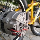
The sliding mechanism is made out of an 18v brushed DC motor that is geared to increase the torque and to decrease the rotation speed. Both these features are useful for our camera slider.
Now to mount this geared motor we have made a wooden enclosure on one of the side wooden blocks which acts as a mount for the motor as well as to act as an enclosure for the wiring and the related equipment.
The enclosure is made out of 3mm plywood parts which are then glued to the wooden blocks. Then the motor is mounted to the bottom of the enclosure.
Step 9: Adding the Pully


Now we have mounted a small metal pully made out of an old window slider wheel fitted with some wood in the centre which helps to mount this pully on the shaft of the geared motor.
Step 10: Varnishing the Wooden Parts


To give the wooden parts a classic look and to protect these parts from weather damage over time I have applied multiple coats of clear varnish which brings an awesome finish to all the wooden parts.
Note:
Before doing this varnish process I have secures the aluminium sliding rails and the motor using some masking tape.
Step 11: Rope for Sliding Mechanism


We have used a 1mm thick nylon rope to act as a sliding mechanism belt and make the sliding platfor move from one side to another. The rope is first attached to one side of the sliding platform using a 1 inch long cut screw. Then passing this rope over the pully giving it an addition turn over the pully which increases the grip of the pully over the rope.
The rope is then passed through the sliding platform to the other side wooden block where the rope is passed through a pully which is then fitted to the block using a pair of cut screws.
The rope is then mounted to the other side of the sliding platform using a cut screw. The rope is now ready to transmit the power of the geared motor to slide the platform.
Step 12: Wiring Everything


The wiring is simple.
First off we need a 5mm input adapter to obtain the power from an external power supply rated at 18v to drive the whole mechanism.
The positive supply then goes through a simple switch to turn on off the slider. From the switch thepositive supply then goes to the potentiometer which is used to vary the speed of the sliding platform by increasing or decreasing the input voltage.
The positive supply form the potentiometer then goes to the toggle switch which is employed to select the desired direction of motion.
Two limit switches are used to shut the motor when the sliding platform reaches one end of the slider. The limit switch is connected between the toggle switch and the motor and by using a 1 inch cut screw mounted to both end of the sliding platform we are able to trigger the desired limit switch as the platform approaches to the respective end and thus cutting of the supply to the motor. Thus enabling the user to move the slider in other direction by changing the direction of the toggle switch.
To protect all the wiring from getting in between the pully and the rope I have added a cover over the motor pully and then closed the top of the wooden enclosure.
Step 13: End Results


The final product appears to be a useful tool to take up some great shots even it seem useful to me for making great shot of my DIY projects for my youtube channel .
This Portable camera slider works smoothly and can work in almost any orientation as far as you are able to mount this slider to work in the desired direction. This whole camera slider costed me around 10$ excluding the camera mount as shown in the last pictures.
That turned out to be a a very nice do it your self project.
If you like this project then don't forget to visit my youtube channel for more awesome DIY projects and subscribe to my channel for more upcoming projects.
Regards.
DIY King

Participated in the
Reclaimed Contest 2017


