

Introduction: DIY RGB Smart Bulb From Scratch

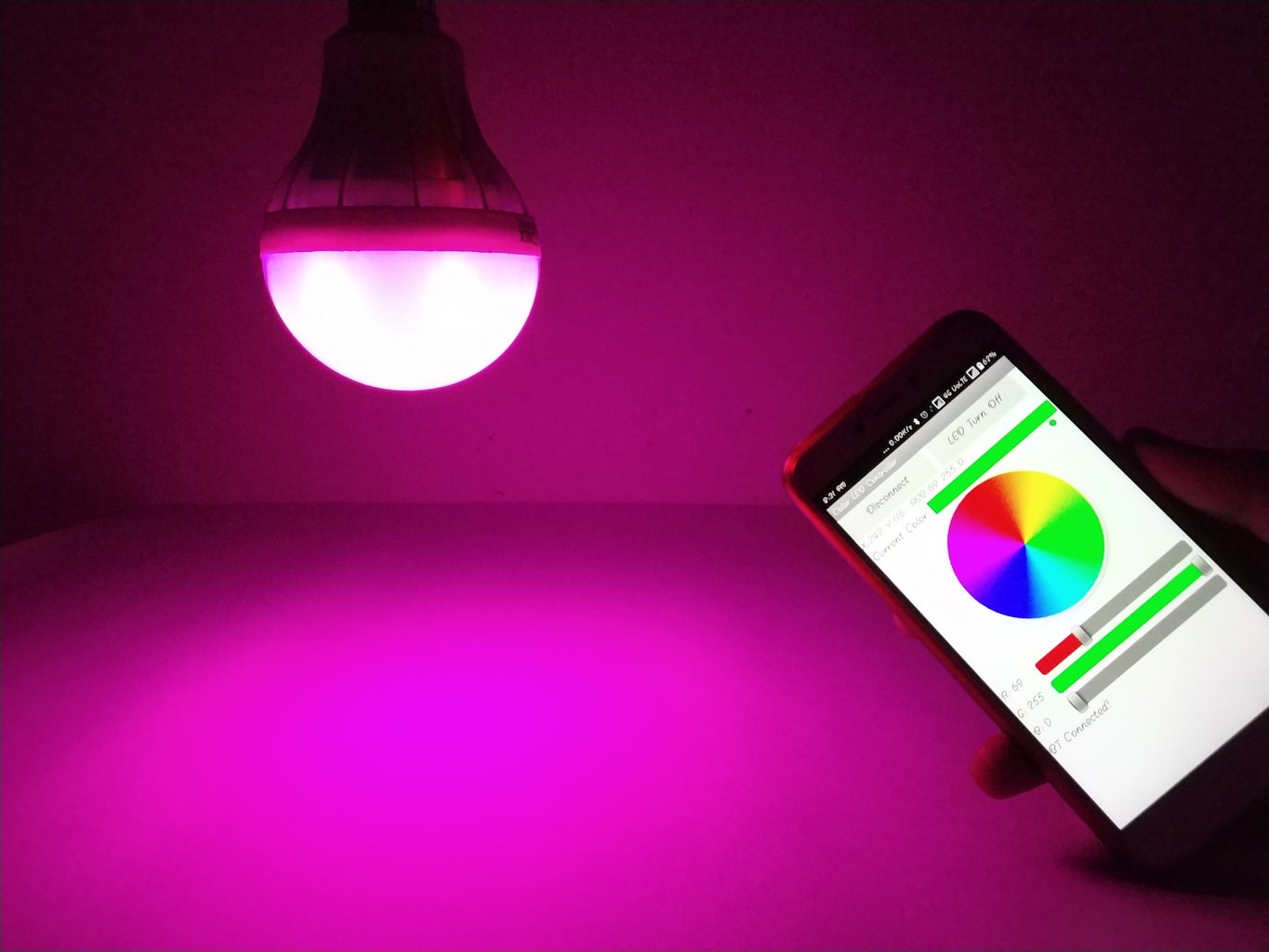

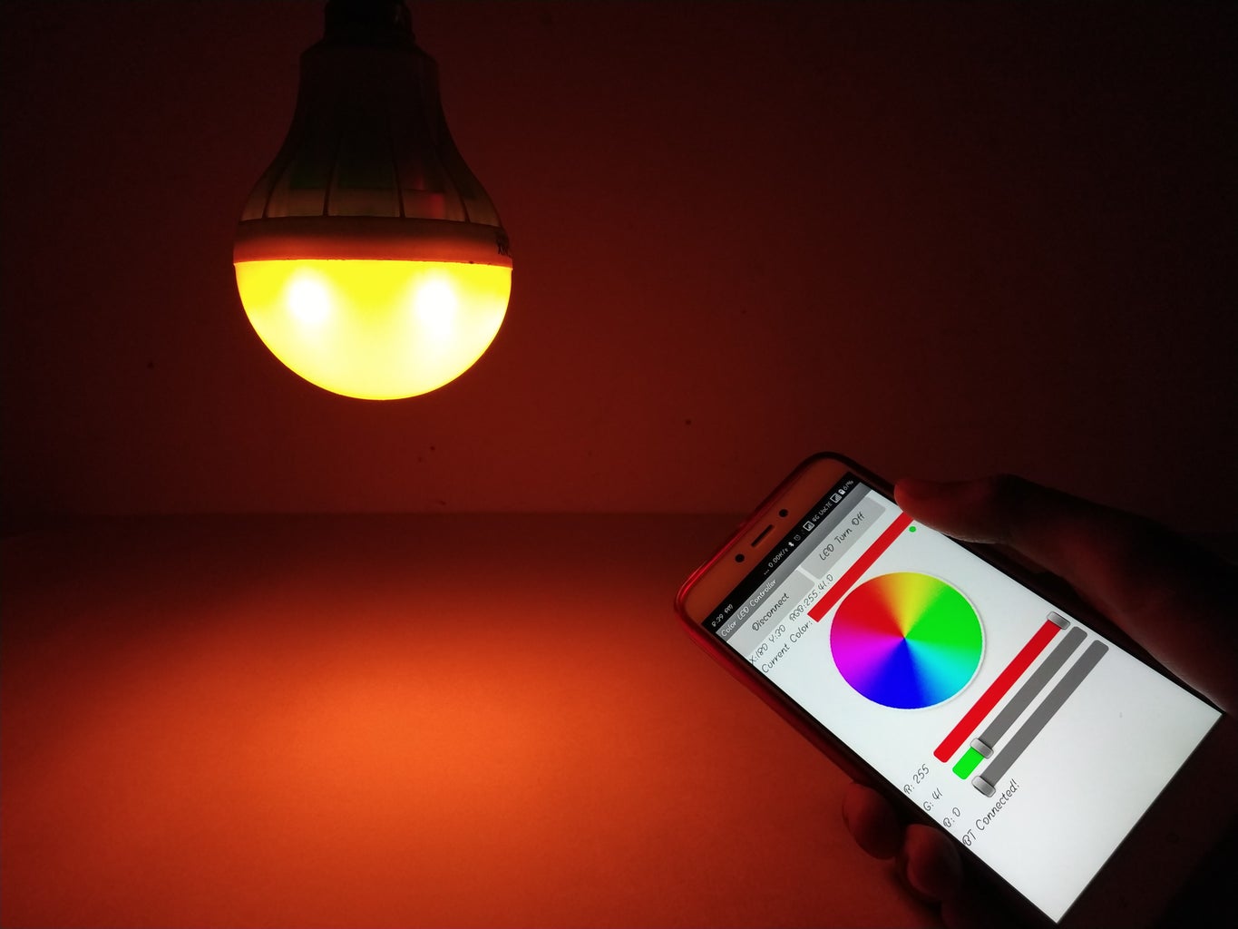


Hello Guys, In this instructable, I am going to show you how you can convert your old or broken led bulb into a smartphone-controlled colour changing smart led bulb. So let's get started :)
Here's the complete tutorial and demo video.
Step 1: Parts List


We need this following parts and tools to make this project.
Parts List:
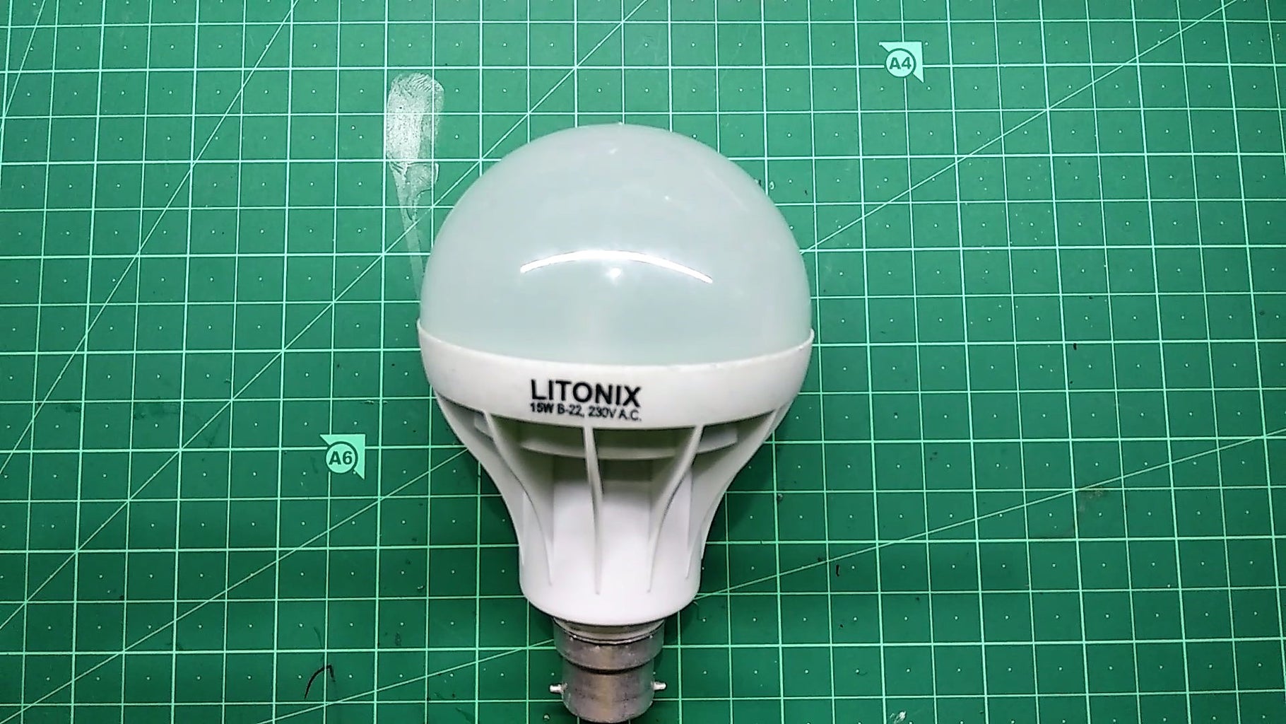
- Old or Broken Led Light Bulb.
- Arduino Nano.
- HC-05 Bluetooth Module.
- Mobile Charger Circuit Board(5v 1A)
- Custom PCB Circuit Board.
- 5mm Common Cathode RGB Led (6ps)
- 100 ohms Resistor (18ps)
- 4.7k Resistor (3ps)
- 2N2222 NPN Transistor (3ps)
- Male And Female Header Pin.
Tools List:
- Soldering Iron And Wire.
- Wire Cutter.
- Masking Tape.
- Hot Glue Gun
Step 2: The Circuit Diagram


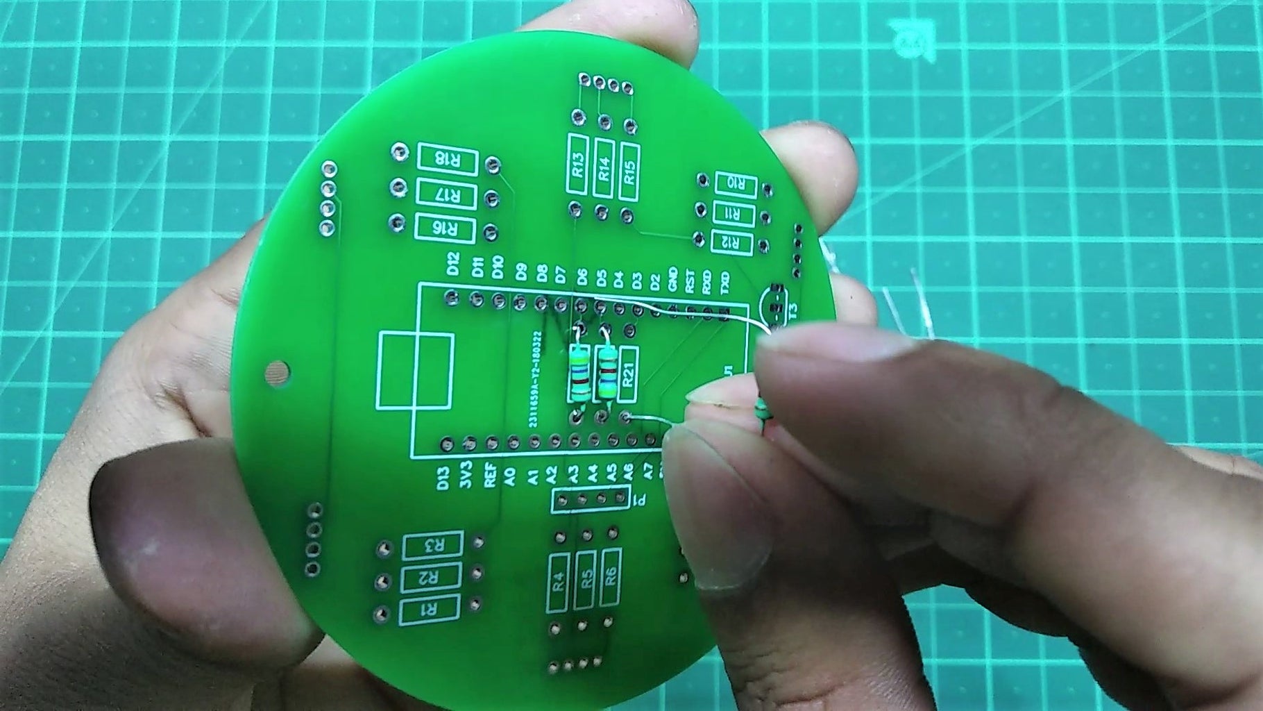
Step 3: The Custom Circuit Board


In this project, I've decided to use custom PCB board. Which will save my time and also circuit complexity, So I order my custom PCB from JLCPCB. It is a great place to buy custom PCB at a very cheap price. here you can get 10 boards only for $2 dollars, which is a great deal.
Attachments

Step 4: Solder the Components


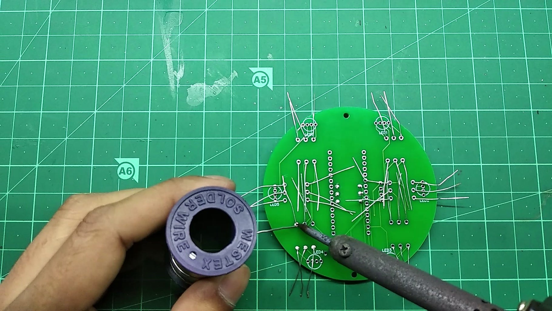


First, We'll start off by mounting all the resistor, Then solder all the resistor perfectly.
Step 5: Mount the Arduino and the Bluetooth Module
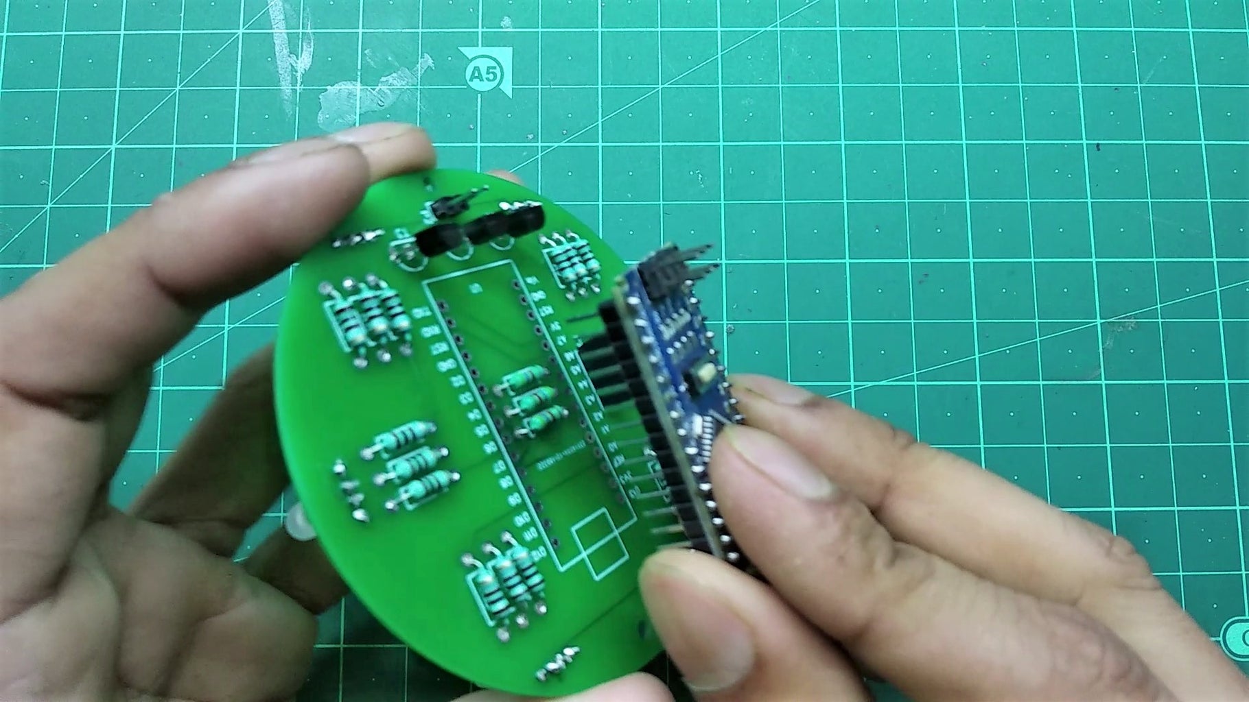


In this step, we'll mount the Arduino and the Bluetooth Module.
Step 6: Upload the Code


In this step, We'll Upload the code to Arduino.
- First, connect the Arduino with PC through USB cable.
- Select the correct port and board.
- Then upload the code.
Attachments
Step 7: Mobile Charger Hack


Here I'm using a 5V 1A mobile charger circuit board as a power supply for this project. At first, remove the USB connector from the circuit board. Then connect two wires to the positive and negative output pin of the charger board. Now connect input AC supply wires to charger input pins as shown in the in above pictures. After that must cover the charger circuit board using the masking tape to prevent from short circuit.
Step 8: Assemble the Bulb

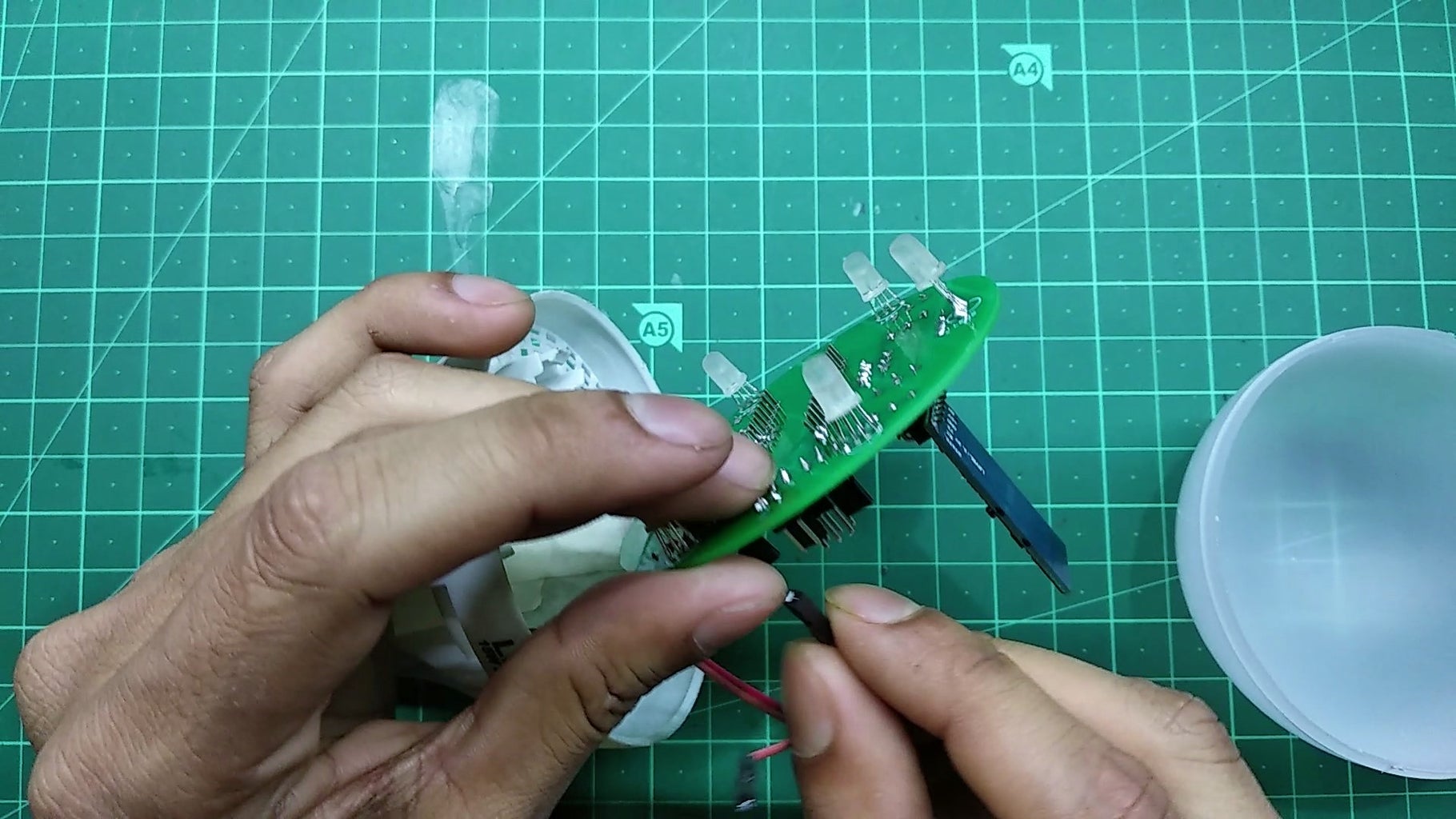


First, attach the charger circuit board using hot glue. Connect the output positive and negative wires of the charger board to the main circuit board. Then mount the main circuit board using screws. now we are done, this bulb is ready to show its magic :D
Later I'll keep updating this instructable.
Thanks for watching project, I hope you liked this project, if you did then please follow me I'll keep posting awesome new projects. Also, don't forget to SUBSCRIBE my YouTube channel.

Participated in the
Colors of the Rainbow Contest


