

Introduction: DIY SIMPLE AUTOMATIC LIGHT USING PIR MOTION SENSOR.


Hi Friends,
How are you ?
i hope you are fine.
Have you seen Automatic lights on houses and Some offices,its cool right.
These stuffs will save power when nobody at in the room and also it will change our home to smart automated home.
The reason I came up with this instructable is ,
Two days ago I found one in a local store . But its cost 50$ . Little bit expensive for me . So i decided to make one.
I just took 3 hours to design and make one . Its really simplest Diy automatic light ever!
it also costed me about 5$ to buy all the parts (the AC bulb is lying around in my home).
If you have a free 1 hours of time and need your home lights up automatically when anyone enter the room.
This instructable definitely for you . We can make one that i'am made.
you just need some cheapest parts from a radio shack or online stores.
So,what you waiting For, lets get start.
Step 1: COLLECT THE PARTS.


Now in this step we need to collect some parts to do this Diy automatic light.
I bought almost all parts from local store,also made some modules myself you can make one (i will give the links to my instructable its really low cost to make).
So,here the list of the parts you need to collect :-
HARDWARE:
PIR motion sensor
5v Relay module(If you need to make one yourself click here.)
Mini breadboard.
Jumper wires(male to male and female to male)
Ac bulb
LM7805
10mf capictor(2nos)
IN4001 diode
LED (green)
220ohms resistor
After collect every parts lets jump to next step !
Step 2:


Step 3: POWERING THE CIRCUIT.
We done almost friends !.
Before implementing the circuit to your house.We need to check if it is working or any problem with circuit even a wrong connection.
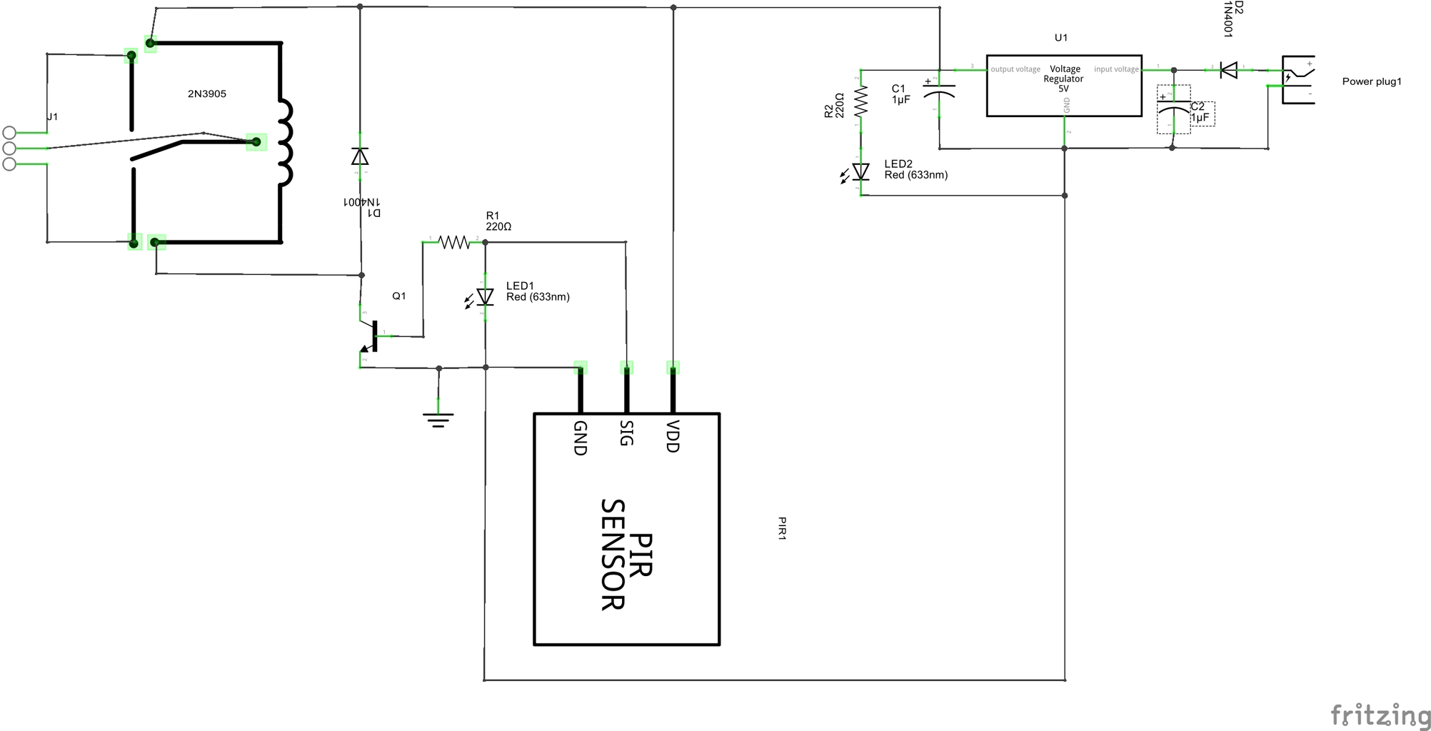
Here we going to use a 5 volt regulator that we mentioned in the last step before!
If you give more than 5 volt to the PIR motion sensor,it will damage. So, remember 5 volt is the maximum volt for the PIR motion sensor.
I USED MY DIY 5 volt REGULATOR, YOU CAN USE ONE IF YOU HAVE. ELSE MAKE IT ALONG WITH THE CIRCUIT SCHEMATICS.
Give the power to the circuit.
NOTE: don't connect the Ac bulb to the relay module this time .
Now turn ON the circuit. check the motion sensor working by put your hand infront of the sensor.
just wait for a 4 second(there will be a delay if the sensor working at low sensitivity,we can adjust later)
if the relay module turning ON(a switching sound, and the LED light up)
If not suddenly turn OFF the power and check for any wrong connections.If found one , then correct it and also double check once more.
then re power the circuit and test the motion sensor works(if not some thing wrong with your sensor, recommend to change the sensor).
if it works !!!!!!!!!
We made it GuYS .............
Step 4: CONNECT THE BULB TO THE RELAY MODULE
We finished everything, now its the time for connect the bulb to the relay module as shown in the above schematic diagram.
Connect the power supply, thenTurn ON the circuit and test it as we done in the last step.
If there is any delay in Sensing of PIR sensor Just adjust the to potentiometers on the PIR sensor !
IF EVERYTHING WORKS FINE WE DONE !!!!!!!!!!
Step 5: CUSTOM PCB FOR AUTOMATIC LIGHT.(optional)


This step is completely optional !
If you like this module very much you, probably like it because it is simple to make , cheap etc...
i'am not explained the tools needed to make the PCB because its really simple, every one know how to solder a PCB.
So, we can make our own PCB, i'am not going to explain so much . we can make This module on PCB in two way.
TOOLS NEEDED TO MAKE PCB
General purpose PCB(optional if you make your own custom pcb).
Copper clad(optional if you make it in a general purpose pcb)
Soldering iorn.
Soldering flux.
Soldering wire.
Hookup wire.
1. GENERAL PURPOSE PCB(optional if you make a Custom PCB using copper clad)
We can simply make this on a general purpose PCB.
1. Take a general purpose PCB the clean well.
2. After that , rub some soldering flux on it.
3. Then mount the components,and solder it.
4. Connect all components each other like in the circuit schematics using hookup wires.
5. Then test the PCB.
NOTE : double check for any short circuit and wrong connection before use it.
2. PRINTED CIRCUIT BOARD USING COPPER CLAD.
now if you like to make your own printed circuit board.
if you don't know how to etch a PCB,then watch the video tutorial here.
1. After watching the tutorial download the software called fritzing(we using this software to design the pcb)
2. After download and install the software download below file called pir_sensorpcb.fzz(it is the pcb design)
3. Then open it with fritzing .
4. Then to print the pcb do as like you saw in the tutorial.
5. After a good etching the PCB use 0.8mm or 1mm to drill the PCB.
6. Then mount the components simply solder it.
7. check for any short circuit and breaks in traces before use it.
So guys we made the Diy automatic light on a PCB , now it is durable and long lasting.
Attachments

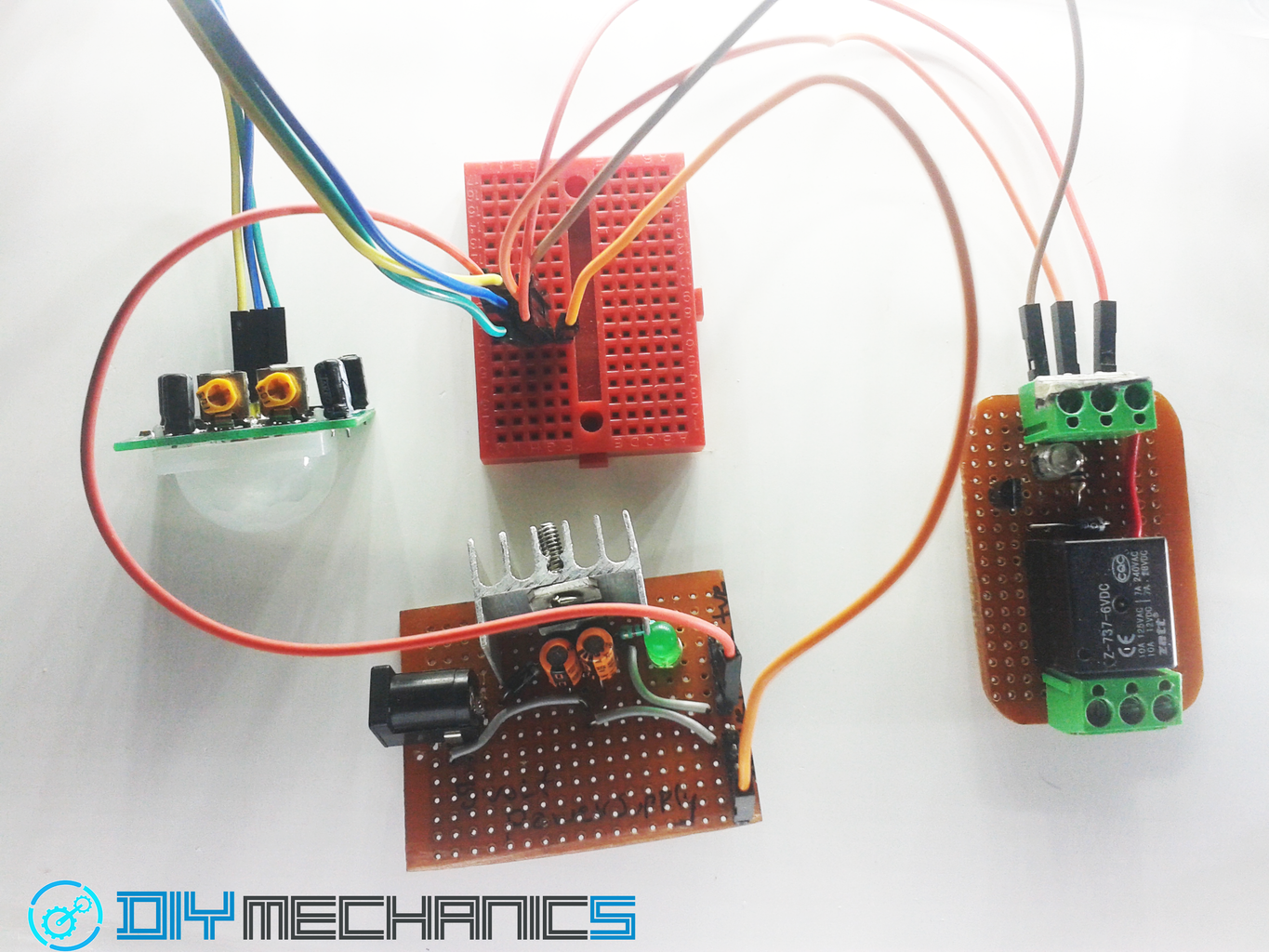
Step 6: WORKING DEMO !!!
We made it guys everything works fine.
Now just mound it your living room or bread board, else any where you want.
see the demo video............
you can also works anything with this module even TV,washing mechine,coffee maker etc......
the opportunities never ends.
Even you can mount it in your car, and when you are sitting in the driver seat the car will automatically start.
else it will not start.
COOOOL THING RIGHT GUYS.....................................
see you in next instructables

Participated in the
Automation Contest 2016


