

Introduction: DIY Wind Tunnel 2.0, Project "Paperclip"


"The true method of knowledge is experiment" - William Blake
Towards the end of my junior year, my physics teacher challenged the class to work on a final project that would encompass all that we have learned over the year. We had the choice to learn something new, hone a specific discipline, or develop a method to teach the class about a specific subject. In my mind, I knew that I wanted to find a project that encompassed all three of these criteria. This is how I, along with my classmate Ian Kelley, stumbled upon building our first wind tunnel.
Going into this project, we did not know much about wind tunnels, much less how to build one. After our build, we published a guide on Instructables (available here). Within a few days, it grew on a humongous, unanticipated scale. We were able to receive feedback from individuals that were experts in the field of aerodynamics and fluid dynamics. Inspired by their support and constructive criticism, we went back to the drawing board and asked ourselves what could we do to improve our design. After a long iterative process, we were able to compile and assimilate the suggested ideas and started to build. This ible is meant more as a guide to learn from and is meant to work in tandem to the first guide. Some specific details may be left out intentionally to allow for a certain degree of independence and creativity. Experiment!.
Without a further ado, I would like to present our DIY Wind Tunnel 2.0, Project Paperclip.
Step 1: What Is a Wind Tunnel?


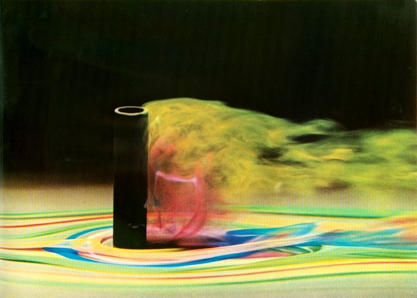
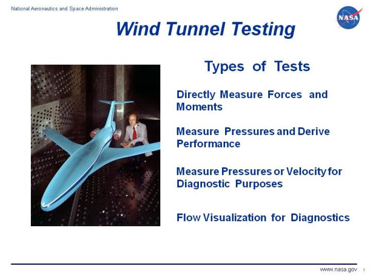
Although wind tunnels are not as prevalent as other high precision instruments, they have huge implications on the everyday lives of everyone and everything on Earth and beyond. From cars, airplanes, and space-faring vehicles, to buildings, bridges, and skyscrapers, knowledge and understanding gained from wind tunnel research provides a conduit for mankind's drive for innovation.
Now how does a wind tunnel work? Well the physics behind it are based off of the work of Daniel Bernoulli, a Swiss physicist. Many might remember him from the equation that you learned in physics back in high school of constant= P + 1/2 p v^2 + p g h. An equation he helped contribute to, the continuity expression in physics of A1V1=A2V2. This provides the foundation of wind tunnels by showing how if you decrease the cross sectional area, your speed subsequently increases.
Photo Credits:
#1: http://www.seriouswheels.com/pics-2005/2005-Pagani-Zonda-F-n-Wind-Tunnel-1600x1200.jpg
#2: http://airfactsjournal.com/files/2012/09/wind-tunnel.jpg
#3: http://www.efluids.com/efluids/gallery/gallery_pages/HW019/Werle_19.jpg
#4: http://www.cdn.sciencebuddies.org/Files/503/9/wind-tunnel_F.jpg
#5: https://www.grc.nasa.gov/www/k-12/airplane/Images/tuntest.jpg
#6: http://3.bp.blogspot.com/-9omxPSGsnr4/UM9nx3kN0sI/AAAAAAAAT8M/iRJpWE3bkiA/s1600/open-circuit-wind-tunnel.jpg
Step 2: Design


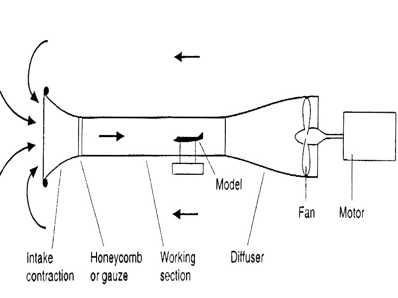
The design of a wind tunnel is very simple, consisting of four main parts: an intake section, a testing section, a diffuser, and a fan (or array of fans). In addition to these four components, there are small parts of the tunnel that make it either more accurate or easier to gather data. As with most well-designed engineering systems, all these components come together to accomplish the task of helping one visualize and understand the aerodynamic properties of various objects and designs.
After much research and understanding the much appreciated feedback from my previous guide, I was able to design a more adequate tunnel. I have attached my plans in as an image and as a pdf so feel free to check those out. If you have any specific questions, please contact me and I will be glad to help out in any way.
Photo Credits:
#2: http://www.grc.nasa.gov/WWW/k-12/airplane/Images/tunpart.gif
Attachments

Step 3: Materials + Tools


One of the major goals of the project was building an accurate and precise instrument for flow visualization whilst keeping the cost down. By using as many recycled materials as possible and creatively using the money allotted (including using many coupons), we were able to successfully keep the cost of the project to under $100 USD.
~~~Materials:
-Foam board (also know as Foamcore)
Large-Medium
*Note: a cheap alternative of cardboard can be used also
-Old Box fan
-Tape (I prefer different types for various applications)
-Duct-Masking
-Scotch
-Packaging
-Black Spray Paint
-Elmers glue
-Hot glue
-Lexan
-Construction Paper
-Christmas light
-Straws (a lot)
-Styrofoam cups
-Aquarium tubing
-Dry ice (18+ to purchase)
-Wire coat hangers
-Christmas Lights
-Hot water
~~~Optional Materials:
-Sylvania MOSAIC™ Flexible LED Light Strips (link here) (Replaces: Christmas light)
-Fog Machine (Replaces: Dry ice)
~~~Tools:
-Dremmel
-Sand Paper
-Scissors
-Safety Glasses
-Ruler
-Measuring tape
-Jig Saw
-Work Gloves
-Exacto Knife
**This is my version of the BOM (Bill of Materials) & tools. It is meant to be more of a guide than an item by item checklist. Many tools/ materials I used can be replaced with similar things and will differ depending on given budget, resources, etc.
Step 4: Intake


For the intake component of the wind tunnel, we based the design of our intake on various sources and principles. While researching about the way other wind tunnels are designed, we encountered that many of the tunnels had intakes that similar to a bell shape or like the profile of speakers. This design is advantageous since it helps amplify the sound waves into the air from a compact source. For the tunnel, the opposite effect is achieved with this design, taking in a lot of air and channeling it into a directed flow to the test bed of the tunnel.
The intake additionally functions to speed up the air incoming due to the conservation of energy, where A1V1=A2V2 (A=Cross sectional area, V=Velocity of fluid). When air enters the tunnel, it has a larger area and slow speed, but when the area shrinks, the speed increases. As a result, the overall speed of the air across the test section is increased by a certain factor. The design increased speed by a factor of two. However, I am certain that this factor is a rough estimate since the density of the air is assumed to be constant and uniform with the friction between the air and material is overlooked.
Here is a great resources for further understanding this concept behind this pat of the wind tunnel: Link
To delve into further detail, here is a great resource provided by the American Society for Engineering Education: Link
Step 5: Straws, Straws, Straws. the Flow Straightener


The straws are integral to the wind tunnel. Put simply, the array of straws allow for the turbulent air to flow into the wind tunnel smoothly, achieving what is known as laminar flow (smooth flow). Here is a really good visual that I found that explains the difference: here.
When I was making my flow straightener, I recall learning from feedback on my last guide that the dimensions of the honeycomb array of flow straighteners should fall within a certain range of values dictated by an equation known as the Reynolds Number (wiki link). Essentially, the equation goes as such: "Re= ρvD/μ, where ρ is the density of the fluid (air in our case), v is the velocity, D is the diameter of the pipe the fluid is going through, and µ is the dynamic viscosity" (Instructables user Hawkeye_bkj [Thank you for the help]). It was also recommended that I achieve a Reynolds number around 2300. With the dimensions of the given straws that I bought and some research, I was able to determine that I needed roughly have a fan that would be able to reach 5m/s (11.2 mph). This was wonderful because during trails with my teacher's wind speed indicator, I was able to reach a value close to 11.2 mph with slight variations that would put the Reynolds number a tad lower. But that was something I was able to live with.
Making the honeycomb array took quite a while. I ended up going through I would say 8 or more packets of drinking straws. I would cut the straws in thirds into roughly 7cm sections and line them up for gluing. Since there were literally a few thousand of straws to cut, I did not bother making it terribly accurate, compensating by making the exhaust of the straw line uniform but not the intake (see image 2, the back vs image 6, the front). Layer upon layer, I slowly glued the straws together with Elmers glue and eventually resulted in an array that looked beautiful. This array was designed to fit into the connector between the intake and the test section.
Step 6: Test Section (Part I)


This is the first iteration of the test section that I ended up using. For many professional labs, this section of the wind tunnel often swapped out with different tests that the lab plans to run in them. Sections may include holes for instrumentation or space for subjects to be placed into and often time vary.
Key attributes that went into the design of this included:
- A sliding door of Lexan to put test subjects inside
- An overall cross section of a octagon to ensure less dead spaces of air
- Modular
- Christmas lights
- Integration of the smoke visualization
- Ability to manipulate the smoke exhaust
The basics of this component was made from 4 pieces of foamcore, each 12" X 30" with one piece that included a hole 1/4" smaller than the 4 sides of the Lexan sheet to ensure that it would not fall in. This was supplemented with 4 long pieces that formed a 45-45-90 degree triangle with the square cross section, making the shape an octagon. Two leftover Lexan sheets were cut to the same width as the long pieces to act as a clear bridge between the sides. The integration of lights within the tunnel were added along with a black construction paper backdrop to optimize visualization of the smoke.
This was a relatively simple design and cheap. More emphasis was placed on having a working design versus having it look ascetically pleasing. After all, form does follow function.
Step 7: Test Section (Part II)


The second iteration of the wind tunnel test section was far superior than the second one. Not only was it able to properly perform the function of the test section, there was much more satisfying balance between form and function.
Key attributes that went into the design of this included:
- Professional lighting with LED strips
- Clean look
- No tape, all glue
- Smooth to touch
- Modular
- A proper, permanent background that provided a good contrast to the smoke
- Addition of the top sliding door so that objects can be placed from both the top and bottom
- Ability to view the flow from the side and the top
- Basic drip-proofing (from the smoke generator mix)
Built off the original test section, I redid the corner panels with a proper chamfering to ensure a flush, smooth joint between the walls and the side panels. This was glued together instead of taped to add a more professional look to the whole attachment. Furthermore, I decided that the construction paper was insufficient for the background since it would easily flare up and had an odd look to it so spray paint was used to make the background. Another opening was added to the top of the test section so that flow could be visualized from the side of the model and the top, helping further reveal the mysteries of aerodynamics.
As with all science projects, experimentation is key. I do not think I would be able to jump directly from the second iteration of the test section without learning from what worked and did not in the first iteration. There is still room for improvements and perfection is hard to obtain. In the end, it all comes down to the standards that one personally holds with craftsmanship and what is to be gained from the experiences learned. It is all a learning curve.
Step 8: Diffuser


Incoming air from the test section enters the part of the wind tunnel known as the diffuser. It is a section of the wind tunnel that opens up slowly, increasing the cross sectional area slowly over a long distance. Essentially, the role of the diffuser is to slow down the air that speeds past the models in the test section. According to the website that provides great animations for each part of the wind tunnel (the diffuser one available here), the speeds are slowed down such that the fans do not have to run as fast which results in a cheaper operation of the fans. This makes sense using the continuity equation (A1V1=A2V2) since with as the air enters the diffuser, A1 is low and V1 is high and when the diffuser opens up at the other end, A2 increases resulting in a decreased V2. Slower fan speeds results in less power output by the motors which in turn results in less usage of a power source and more money saved.
Key attributes of my diffuser was that it is very modular, being able to fold up from being a large roughly 15" X 15" X 40" rectangular prism to a 30" X 1" X 40" flat board. After my experiences with having to transport the instrument, this attribute has been really useful in terms of cargo space and ease. Decorations were also added to add some color and life to the bland sides.
This was made from 4 pieces of trapezoidal shaped foamboard, with dimensions of Base1=12", Base2=15", and Height=40". The technique used to combine the pieces together is similar to the methods used in step 4, the intake.
Step 9: Smoke Generator & Flow Control


Although seemingly simple, generating the smoke trails that help visualize the airflow around objects is difficult. I have tried many variations of material (incense, fog machine, dry ice, etc) and vessel (glass, Styrofoam, plastic, etc) with none of them being close to perfect. The set up that I utilize currently is the cheapest and simplest one that I have found in relation to the smoke being created. A really good trail of smoke can be created from the dry ice + hot water combo with the drawback of having to replace the solution with new ice and water after a certain time. I would recommend it over using incense or a fog machine as of now due to the dangers involved with the machine and the dizziness induced by the smoke. The way that flow is controlled was developed by my genius partner, Ian. Using simple wire coat hangers, he was able to unbend them such that they took the shape of a hoop with a small loop on the top. By placing half into the tunnel, we are able to manipulate the direction of the smoke by pushing it either left or right, up or down, or a combo of both. Versatility is a key attribute to this design.
For making the device, 3 Styrofoam cups were used. Two of them were first stacked within another with a hole added to the side for the tubing. With this, the top of another cup is sliced off and added to the original set up inverted such that a sealed compartment can be achieved. Some plastic wrap was added so that the volume of the container would be smaller, allowing for the smoke formed through the reaction between dry ice and hot water to flow through the tube easier and not get stuck in the vessel.
***Exercise safety while working with dry ice and hot water!
Step 10: Fan Modifications


It is essential that the airflow of the fan is unobstructed from any baffles or parts that restrict the flow. Especially since the fan I used is an old fan, the efficiency of the fan was already low. By freeing up the fan, I would ensure optimal flow without altering the fan electrically. The aesthetics of the fan was also vital to the wind tunnel as a whole since it was an integral part to the instrument as a whole. Therefore, it was spray painted with a black and gold color scheme (our school's colors) and a red top for cautionary purposes.
A cone made from construction paper was also prototyped and added to the fan because on the intake side of the fan, there was an area of dead space where the overall flow could be disrupted. The method that I used to construct the cone is outlined in the following link, available here. This step may even not necessary if you feel that it will not matter since the effect of not having it is negligible.
Step 11: Experimentation


Although this is not a physical step to making the wind tunnel, experimentation is essential to any engineering process. Great ideas or solutions to problems are not always obtained from the first go. Making things takes a great deal of trial and error, often times resulting in more of the latter than the former. However, if thought of as a learning curve, mistakes often lead to alternate approaches to problems which eventually leads to successes.
In these sequence of images, we experimented with three things, the flow visualization tool, the unrestricted fans with the baffles gone, and the construction paper cone that eliminated the dead space and turbulence of the intake. We were able to conclude that the although the fan modifications helped increase the flow and speed of the flow output, it could be further refined with a longer cone and hermetically sealed fan and tunnel connector. The smoke visualization proved to be ineffective with a glass jar since the ice would easily freeze the container and we feared it shattering the whole jar. This led to development in using Styrofoam cups which are insulators and less likely to lose the cold due to conduction.
Although this Instructable may outline the key elements to my tunnel, it leaves plenty of room to experiment with various designs that are tailored to a project's specific needs.
Step 12: Testing


The main objective of building this wind tunnel was to be able to educate people about the implications of aerodynamic testing and inspire youth's interest in STEM. As a testing device, we would be also able to demonstrate our instrument to groups of students and teachers, helping them visualize and understand the complex study of aerodynamics.
We ran many different types of test in our tunnel, ranging from cars and planes to sponges and balls. It was exciting to see the aerodynamics of unconventional objects and verify the visualization of conventional items.
These are a few of the chosen images and videos that were taken of the tests, taken either by my friend, Pranav or I. To see more of the videos that were not provided on this guide, click here for the whole playlist of the filmed tests.
Step 13: School Exhibit & Robotics Expo


Since the project was sponsored by our high school AP Physics teacher, we brought in the wind tunnel to show students. This exhibit was timed such that it would be right before students learned about the basics of aerodynamics and drag. It helped better explain what factors go into the B in F=-bv.
I also had the opportunity to display my tunnel when my school's robotics team had the chance to run a Junior FLL Expo. There hundreds of elementary school kids and they all enjoyed seeing the tunnel. Additionally, many parents were excited themselves about the wind tunnel, often asking more questions than their kids. GO STEM!!!
Step 14: Maker Faire Exhibit


On December 7th, 2013, Ian and I demonstrated our project at San Diego's First Annual Mini MakerFaire. This opportunity was presented when I learned about MakerFaire from searching local science fairs. I originally planned to enter the project into a science fair but found the qualifications too limiting and stringent. Project Paperclip called for more freedom and the DIY aspect versus the graphs and charts poster boards.
We were one of 120 exhibitors at the Faire, the first of it's kind at San Diego but surely not the only one ever. The maker movement is strong in these parts and we were glad to be a part of it.
Additionally, we had the privileged of meeting Mr. Dale Dougherty, founder & CEO of MAKE Magazine and the organizer of MakerFaire's around the world. We were stunned initially when we met him, missing the opportunity to take a photo with him (sadly). However, he did mention how great of an idea our project was, and it's novelty. Meeting him was the highlight of our day.
I hope to see future events grow in both exhibitors and visitors. It would be great to see what a real MakerFaire, such as the one in San Francisco, is like.
Step 15: Finale


Working on this project has definitely been one of the best things that I have ever experienced. From visualizing the aerodynamics effects of different objects and meeting Mr. Dale Dougherty of MAKE Magazine at SD Mini Maker Faire, to seeing kids excited about something as complex and arcane as aerodynamics and having fun building, this has been a wonderful journey. I have learned a lot from my mistakes and successes during this project. I genuinely owe the knowledge I have gained to Instructables and the community behind this wonderful website, allowing me to show to the world what I have made. Thank you to my partners Ian Kelley and Ned Anderson for helping make this build possible and to Jonathon Boyle and Pranav Santan for assistance and guidance.
Most of all, thank you (the reader) for being a part of this wonderful,supportive community of doers and have a wonderful day.

Third Prize in the
Full Spectrum Laser Contest

Third Prize in the
Scientific Method Contest

Participated in the
Green Electronics Challenge


