

Introduction: Dancing LED
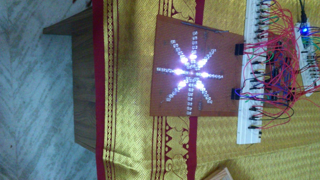


To build a 8 by 8 LED pattern as shown in the figure and program it using Mbed microcontroller NXP LPC1768 to get various sequence of the LED lightings. A total of 64 LEDs are used which are used in rows and columns and then programmed to get different sequence of LED lighting.
Attachments

Step 1: Construction of LED Circuit


To build a 8 by 8 LED pattern as shown in the figure which can be programmed using Mbed microcontroller NXP LPC1768 to get various sequence of the LED lightings.The pattern is as shown in the figure, there are 8 branches and each branch will contain 8 LEDs with a total of 64 LEDs in the entire pattern.
The LEDs in each branch may have the same colour or they might have different colour the choice of the LED colours is free. In our project we used the following sequence from inner most side - Blue Green White Red Blue Green White Red (BGWR).
All of the 64 LEDs should be individually controllable, that is they could be individually turned on or off so as to get different sequence of colours.
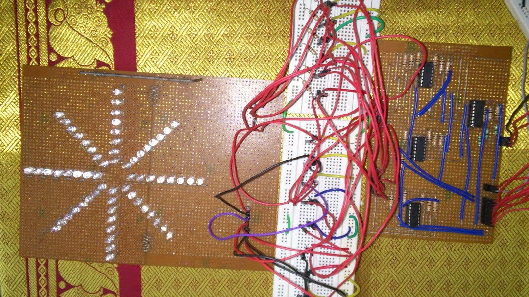
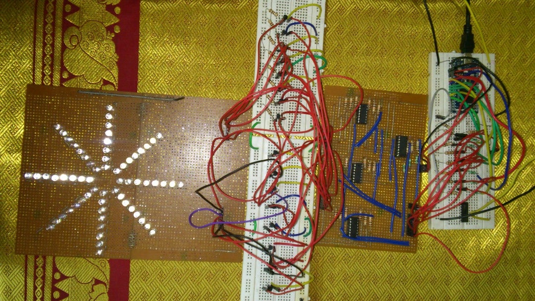
The circuit diagram and the actual soldered circuit is shown in the diagram.
Step 2: The NOT Gate and the MOSFET Driver Circuit


components required :-
16 Mosfets (2n7000a), Resistors*28 (100k ohm), Resistors 100 ohm(11), Resistors*8 (100 ohm or 220 ohm or 1k ohm depending on the brightness desired we used 100 ohm). In this circuit I made use of 3 NOT gate IC, 1 3 to 8 DMUX IC, 16 Mosfets, resistore and wires. The Not gates used are simply as an intermediate stage between the Microcontroller pin outs and the mosfet base and this is not really necessary as the base of the mosfet has high impedence and the microcontroller can be used to drive them directly.
Resistors are used as pull down resistors so that the outputs are not left floating. This ensures a logic 0 at the output even if the input is floating. DMUX IC is an optional component, the project can be done without using this, but the use of DMUX results in a considerable decrease in the output pins from the MBED. The DMUX we used is 74HC138. This dmux is an active low dmux which means that when line 1 is selected it will be at 0 volt with the other 7 lines at +5 volt. There are 8 + 3 pin out is required from microcontroller out of which 8 are required for the 8 column select not gates. 3 are for the row select 3 to 8 dmux.
The MOSFET driver circuit is as shown the input to the base is given from the microcontroller or the output of NOT gate( if it is used as intermediate stage). Then the drain of the mosfet is pulled to +5v with a current limiting resistor, this resistor determines the brightness of the LED. From the drain another connection is given to the cathode of the LEDs shorted together. the anodes of the LEDs which are shorted are connected to another MOSFET and the base connection for this MOSFET also comes from the pin out of microcontroller or NOT gate. The source of both the MOSFET is grounded. +5 volt can be given using any 5 volt Mobile charger or a simple regulated power supply.
The circuit shown explains the connection for a 4 by 4 LED matrix, the circuit is similar to that of the 8 by 8 actual circuit but the arrangement is not in the star pattern, this circuit is done only for the sake of understanding, and the same circuit can be extended to the 8by 8 LED star pattern consisting of 64 LEDs using 8 more MOSFETs.
Step 3: Microcontroller and Programming

For the purpose of getting different lighting patterns we have to create the code. Any microcontrollers that has more than 11 digital I/O pins can be used such as Arduino, Atmega, NxpLPC1768, Pic, etc. Also this can be tried using microprocessors.
I have tried the project using NXP LPC1768 mbed microcontroller and Atmega8. Although the coding changes slightly the basic concept of programming algorithms remains the same.
The flowchart shown in the diagram throws some light on the programming aspects of the microcontroller. This flowchart is only for the sake of understanding purpose and the actual code written is a huge variation of it.
The algorithm using interrupts can be briefly described as follows:
1. Define 11 Output pins
2. Define the interrupt
3. Assert the Digital output of the necesary pins to high or low as required
4. Change the interrupt period if required

Participated in the
Explore Science Contest


