

Introduction: Designing a Roasting Tray in Fusion 360


Let's make a coffee bean roaster!
FirstBuild is a pretty sweet community of designers and engineers where anyone can contribute to the design and production of GE Appliances, and this month they're running a design challenge for a coffee bean roaster that you can use with any common kitchen oven - you can learn more about the specs & requirements for the coffee bean roaster here: https://firstbuild.com/JBerg/roast-coffee-in-your-...
This is a quick intro of how to approach designing things in Fusion 360, specifically a tray for a possible coffee bean roaster designed by Justin Brown at FirstBuild. The design is basically a circular tray with a perforated insert. A motor turns four wires to keep the beans turning and separate any debris. A fan on the bottom blows air to cool the beans on the other side of the perforated insert. To learn Fusion, we'll just be looking at the circular tray and insert.
I've really enjoyed using Fusion 360 - it's a very different approach to CAD, and some people will find it very freeing. It's important to note that it's free to startups, students, and enthusiasts/hobbyists, so you can get it for free here.
So let's get cracking'!
Quick note: all of the steps have an animated .gif - if they're not moving, or you having trouble seeing them, you might have to look at them in a full browser on a computer). I'm not totally certain where they work and where they don't.
Also, an Instructable for rendering this model: https://www.instructables.com/id/Render-Models-In-F...
Also also, an inscrutable for sharing publicly: https://www.instructables.com/id/Share-a-Model-in-F...
Step 1: Quick Tour of Fusion

If you're curious for a fun/inspiring video describing Fusion you can find one here:
Basically, Fusion 360 is Autodesk's newest professional product design software - it's pretty popular among engineers, designers, and makers - great for modeling, sculpting, rendering, simulations, and CNC machining.
I didn't want to overwhelm with "getting started" stuff, but here's a picture of how I'd describe the interface. To view a larger version: http://i.imgur.com/5VW5zoa.png
It also has a pretty responsive forum with people asking questions here: www.fusion360.autodesk.com/forums
And all the technical learning stuff here: https://forums.autodesk.com/t5/fusion-360/ct-p/123...
And some neat inspirational user-submitted designs here: https://fusion360.autodesk.com/projects/
Up next, the meat and potatoes!
Step 2: Create & Activate a New Component

Here we go!
Start by making a new component. Right-click the full file at the top of the browser, and choose "new component." You can then name it by clicking twice (not double-clicking) on its name, and typing a new one. If you can imagine the full file that you right-cliicked on being the "assembly," each component is essentially a "part" in that assembly. And anything inside that component is essentially a "piece" of the "part." (Pieces could include bodies, construction geometry, sketches, decals, etc).
Next, hover over the new component and click the white dot next to it. This means we've activated the component. So whatever we make now will show up as a piece inside this part, rather than a piece inside the full assembly.
Step 3: Start With a Cylinder

Think about the best way to start - if you look at the design we want to model, it's basically a hollowed-out cylinder with a rounded bottom edge. So let's start with a cylinder.
Choose "Cylinder" from the "Create" menu. The first thing you need to do is pick a plane to start your cylinder on. Anything you're creating in Fusion's 3D space needs a starting point somewhere in space. Choose the "Bottom" plane (x-y plane). Now you'll need to draw a circle. Click the origin once and let go. Draw your mouse away from the origin to see a circle forming. Type in a specific dimension of 9in and click "okay." Even if your document default display is mm, Fusion still recognizes "in" and converts the unit for you. You could even type in something like "1in + 3mm" and it would calculate that value for you.
Note that once you click "okay" a "Bodies" folder appears in the new component in your browser (probably called "body1"). Just keep in mind that this cylinder body is essentially a "piece" of the component (which is essentially a "part" of the full assembly).
Step 4: Filet the Cylinder

To get a rounded edge along the bottom, choose the "filet" tool from the "Modify" menu. Then, click on the bottom edge. Like most tools in Fusion, you can click and drag the arrow manually, or type in a specific radius. Go ahead and type in ".25in"
Step 5: Hollow Out the Cylinder

Next, we want the cylinder to have an open top, rather than be solid.
Choose the "Shell" command from the "Modify" menu. As a quick tip: if you don't know what a particular tool does, just hover over it for a pop-up description of what it does. Once the dialog box pops up, we can click on the face of the cylinder that we want to be open.
Click on the top face.
Again, you can click and drag the arrow to adjust the thickness, but for this exercise, we can just type in ".06in" to match Justin's original design. Then, click okay.
Step 6: Cut Holes for the Shaft and Fan (create a Sketch)

Next, we need to cut a couple of holes to be cut into the tray - then it'll be ready for us to design the insert!
Anything you try to do in CAD can likely be done a ton of ways. There's a specific "hole" tool under the "Create" menu, but one of the most common ways is to draw two circles and cut them through the part. That's what we'll do.
Drawing circles requires us to create a sketch. Under the sketch menu, choose "create sketch." Then, click on the inside bottom surface of the cylinder. This will allow us to essentially draw our circles on the inside surface of the tray.
Note that a "sketch" folder has appeared in your component in the browser, and inside it is "Sketch1," the newest "piece" in the component.
And if you're wondering why the tray has turned orange, this is just Fusion's way of coloring the sketch so that you know there's a closed-in sketch. In this case, it's a circle that Fusion has already traced for us from the surface we clicked on.
Step 7: Cut Holes for the Shaft and Fan (draw Two Circles)

Next, draw the two circles.
Click on the "Sketch" drop down menu, hover over "Circle", and choose "Center-Diameter Circle". This lets you define the center-point of your your circle. Click once on the origin, and move your mouse away, clicking a second time to define the radius/diameter. Make this circle relatively small. We'll give it an exact dimension in a moment.
Next, move your mouse over to the right, and make a second circle, this time a little larger. Again, we'll dimension it correctly in the next step.
Step 8: Cut Holes for the Shaft and Fan (constrain Your Circles)

Now we need to lock down the dimensions for the sketch.
Under the "Sketch" drop-down menu, choose "sketch dimension."
Click on the outside-edge of the smaller circle. if you move your mouse away, you'll see it displaying a dimension - this is the diameter of the circle. If you click once away from the circle, that's where it will leave the dimension. You can double-click on it to change that dimension - let's make this one .75in to accommodate the shaft going up the middle of the tray.
Next, do the same thing for the larger circle, only make it 2.25in.
Then, let's make sure the two circles are always 2in apart. Use the same sketch dimension tool to click on the center of the smaller circle, then the center of the larger circle. We're now defining the distance between the two center points. Again, move the mouse away from the circles and click to establish the dimension. Then, double-click the dimension and type in "2in."
Step 9: Cut Holes for the Shaft and Fan (Stop the Sketch & Extrude)

Now that we have our two circles drawn, we need to exit the sketch and cut them out.
You can exit the sketch by clicking "stop sketch" on the sketch palette on the right-hand side of the screen, or (like shown above) click "Stop Sketch" at the end of the toolbar ribbon at the top of your screen. This will end your working on the sketch.
Then, choose the extrude tool under the "Create" menu. Extrude will basically prismatically turn anything 2D into 3D. In this case, it will take your two circles and create cylinders out of them. So, click on each circle, and then drag the arrow down through the tray. Since you're moving through another body, Fusion 360 will assume you'd like to cut away what you're dragging, which is exactly what we want here.
Click "OKAY," and Fusion will hide the sketch and show you the finished part. You can show or hide anything in the browser by clicking the lightbulb next it.
Step 10: Note the Timeline and Browser

Take a second to see what you've done to get to this point. The timeline shows that we've taken 5 actions:
1. Created a Cylinder
2. Created a Filet
3. Shelled a body
4. Created a sketch
5. Extruded a profile
Now, take a look at the browser. We have two results of those 5 actions:
1. A Body
2. A Sketch
You can back and edit any action you took in the timeline by right-clicking it and choosing edit. This essentially takes you back in time, lets you change what you did orginally, and then recalculates remaining steps to update the resulting things in the browser. This seems pretty simple, but is actually a super powerful way to make plan and make changes to a model.
Step 11: Deactivate the Component and Make a New One

To deactivate any component, just hover over the full assembly (at the top of the browser) and click the white dot that pops up to the right of it.
Now, we need to setup a new component for the insert that we'll be adding to the design.
Right-click the full assembly file (at the top of the browser) and choose "new component".
Name the new component (reminder: to do so, click twice, not double-click, on the existing name). Then, activate the new component by hovering over it and clicking the white dot that appears next to it
Notice that your model sort of ghosts out when you do this. This is so that you can design other parts around the ones that already exist, without getting in the way of what you're working on within that component.
Step 12: Create a Construction Plane

Next, we need to define a plane to start designing our insert on. Before, we used the bottom plane that was default in the file. But for this component, we want the body float half an inch above the inside surface of the existing tray.
If you're already familiar with what construction geometries are, just skip over the italicized paragraph below and get straight to the steps for making an offset plane.
If you're unfamiliar with construction geometry, they're basically things you create to design off of. It could be a plane, axis, or point in space. You can create the constructions relative to any geometry that already exists, whether it's construction geometry in the space or it's the side face or edge of a body. Picturing it being anything you can build off - a plane to make a cube on, or an axis to spin a part around.
What we want to do is start our design .5in above the inside surface of the tray. So, we'll choose "offset plane" from the construction drop-down menu, and then we'll click on the the inside bottom of the tray. This will create a parallel plane that we can drag up and down to offset from the original face. Type in .5in and click okay to lock in the plane above the tray bottom.
Step 13: Draw Disc for Insert

This time, instead of creating a cylinder, then cutting out holes from a sketch, we'll save some steps by drawing a sketch of the insert and extruding it in the next step.
Choose "Create Sketch" under the sketch drop-down menu, and then click on the construction plane we just created to start drawing on it.
Choose "center diameter circle" and draw two circles about the origin - one that's .5in diameter, and one that's 8.75in diameter. These will represent the outer and inner boundaries of the insert.
Click on "Stop Sketch" at the right of the toolbar ribbon, or at the bottom of the sketch palette.
Step 14: Extrude New Body for the Insert

Choose "Extrude" from the "Create" drop-down menu.
Click on the profile of the sketch that lies between the circles you just drew.
Extrude upwards .06in.
Click "OK."
Step 15: Prepare a Sketch for Perforations

All that's left to do is cut some perforations into the tray insert. We'll do this by creating a sketch, drawing the holes, and using the extrude tool once again to cut them out.
Click "Create Sketch" under the "sketch" drop-down menu.
Click on the top of the new body we just created for the insert.
Draw a circle 2in from the center of the insert that has a diameter of .15in (we don't want our coffee beans falling through!).
Step 16: Pattern Out a Line of Holes

Next, we just want to get a few more of these in a line so we can cut them through the insert and make a circular pattern around the insert.
Instead of drawing more and dimensioning them, or copy-pasting them, we'll use a pattern for the circle.
Under the "Sketch" drop-down menu, choose the tool called "Rectangular Pattern."
Look at the dialog box to the right, make sure you've selected the box next to "Objects." Then, click on what you want to pattern (in this case, that small circle we drew). Move the arrow over towards the outside of the insert to see the pattern beginning. Choose a distance of 55mm away, and type in "8" for the horizontal quantity, and "1" of the vertical.
Click OK.
Step 17: Cut the Perforations

Next, use the Extrude tool once again to cut the perforations. Just make sure you select all the circles from the rectangular pattern, and extrude them downwards into the insert .06in, so they cut away the material.
Step 18: Circular-Pattern the Holes

Next, we want to circular-pattern the extruded holes all the way around the insert.
Under the "Modify" drop-down menu, choose "circular pattern" from the "pattern" sub-menu.
Make sure the dialog box has "Pattern Features" highlighted next to "Pattern Type." By patterning features, you can actually pattern each hole, rather than full bodies or other geometry.
Then, click on the extrusion in that you completed in the timeline that made cut the perforations.
Next, select the box next to "Axis". Once it's highlighted, choose the central axis of the origin. If it is not immediately visible, click the lightbulb next the origin in the active component in the browser.
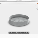
Then, for quantity, choose "50" and click OK. You should see them patterned all the way around the insert.
Step 19: Timeline Check

You should now see 6 actions in the timeline:
1. Offset a plane
2. Created a sketch
3. Extruded a profile
4. Created a sketch
5. Extruded a profile
6. Circular-patterned a feature
And those 6 actions should have resulted in four new "pieces" of your activated component:
1. One body
2. Two sketches
3. One construction plane
Step 20: Rinse & Repeat

I'll leave you to decide just how you'd like your perforations to look. To continue down the same design path as Justin, just repeat the last two steps to create a couple more patterns inside the circular ring of perforations from before.
Step 21: Add Materials

Activate the full assembly, and then all we have left to do is add some materials and render!
Click on "appearances" in the "Modify" menu.
Note: Appearances and Physical Materials are two different things. Appearances have a more options, but are just the way things look in the model and renders. Physical materials actually have density and thermal properties for things like weight calculation and stress/modal simulations.
Appearances work like swatches. Find the one you like, and click-and-drag it to the parts in the model you want to apply it to. It will then appear in the "in this design" panel at the top of the dialog box. If you want to use that same material elsewhere, click and drag it from the "in this design" panel to other parts in the model. To edit a material, double-click on it in the "in this design" panel. You can rename it, change the scale, rotation, color, and reflectance, as well as other advanced changes (including changing out the pattern with a custom .png).
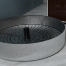
Step 22: RENDER THAT MOTHER


FINALLY - we can make it pretty!
Click on the "model" workspace on the top-left of your screen, and choose the "Render" workspace from the drop-down menu. Here, you can go through and make all sorts of adjustments to the scene and model, and when you're ready, just push the teapot to watch it come to life, or send it off to the cloud to render at a higher quality faster (but this could cost you cloud credits, depending on your license). For a more in-depth tutorial, here's an Instructable on rendering the roaster: https://www.instructables.com/id/Render-Models-In-...
Go to town and have fun!
Also, the Fusion 360 Youtube page has a pretty solid set of tips-and-tricks videos, project workflow videos, and customer videos as well. You can also suggest features, talk to Autodesk employees, and get answers to questions on the Fusion forum here.
Step 23: Checkout FirstBuild
It's a pretty awesome place. They'll be running a coffee bean roaster design challenge for the next few weeks - so feel free to jump into the contest!
Hope this was was a helpful start to modeling in Fusion - Feel free to reach out in the comments section! This was super basic, and there's a ton more to discuss, so feel free to ask about anything.
Thanks!


