

Introduction: Development Board for Attiny84 Microcontroller


This is a development board for Attiny84 microcontroller. Tha Attiny84 chip has 11 pins addressable with the Arduino IDE, 8k of flash memory for program storage, and 512 bytes of RAM available for the stack and program variables.
One feature of the Attiny84 that is very nice for assembly language programmers is unlimited access to all eight pins on the port A registers. They can be used for digital write, digital read, and analog read functions with or without internal pull-up resistors enabled. And four of them can be used for PWM writes.
I am planning to use this board to try to expand my very limited knowledge of AVR assembly language.
You will need:
SparkFun Solder-able Breadboard https://www.sparkfun.com/products/12070
2.1mm barrel jack http://www.adafruit.com/products/373
2 - 10mf electrolytic capacitors https://www.sparkfun.com/products/523
7805 Voltage regulator http://www.adafruit.com/products/2164
2 - 330-560 Ohm 1/4 Watt resistor (purchased locally)
2 - 5mm LEDs, one red one green (purchased locally)
22 gauge hookup wire (I used Red, Black, Yellow, and Green, purchased locally)
9 Volt battery clip http://www.adafruit.com/products/80
9 Volt battery (purchased locally)
Attiny84 micro controller https://www.sparkfun.com/products/11232
14 pin IC socket https://www.sparkfun.com/products/7939
IDC breadboard helper http://www.adafruit.com/products/2105
6mm Pushbutton Switch https://www.sparkfun.com/products/97
Tiny AVR Programmer https://www.sparkfun.com/products/11801
6-pin Socket/Socket IDC cable http://www.adafruit.com/products/371
2x3 male header https://www.sparkfun.com/products/12807
Male Headers https://www.sparkfun.com/products/116
Female Headers https://www.sparkfun.com/products/115
I wish it was possible to purchase all these parts from one supplier to save on shipping but that is not the case. Many of these parts are only available from Sparkfun, and to the best of my knowledge, the IDC breadboard helper is only available from Adafruit.
Step 1: Building the Power Supply


In my diagrams I am using the Adafruit 1/2 Sized Perma-Proto board. I am recommending the SparkFun part because the holes for the power rails line up with a standard breadboard. On the Adafruit part the holes are closer together. This is not to criticize the Adafruit part, but the Sparkfun part is better suited for this project.
The first part to solder is the 2.1mm barrel jack. In order for it to fit it is necessary to cut off the lead on the side of the part. (see picture) Solder the barrel jack into holes A-1 and A-3.
Next solder red and black wires for the capacitors and voltage regulator as shown in the diagram.
Solder the capacitors like in the diagram. The longer positive lead goes in the column with the red wire. The negative lead is shorter and there is a stripe on the side.
Now solder the voltage regulator as shown.
Finish the power supply by soldering the power on LED circuit and the bridge wires to the other set of power rails. The longer lead on the LED is the anode, it goes in the column with the resistor.
Plug in the battery to test your work. The LED should light and the voltage regulator should not get hot.
Step 2: Chip Socket and ICSP Header


The part called an IDC breadboard helper is the In Circuit Serial Programming (ICSP) header. I don't have the Fritzing part so you will just have to imagine that it is there. It looks like the part in the second picture. The third picture is it's pinout.
Solder the In ICSP header into Holes E-14 through E-16 and F-14 Through F-16. Wrap a small rubber band around it to hold it in place while soldering the first pin.
I don't have the Fritzing part so I used a 556 timer to represent the 14 pin IC socket.
Solder the socket, the notched end points toward the power supply.
Solder the wires to the power and ground rails, and the wires connecting the chip to the ICSP connector, follow the diagram.
Step 3: Reset Switch and Indicator LED


Solder the circuit for the reset switch, follow the diagram.
The onboard indicator LED is optional, some people want it and some don't. I put it on Arduino pin 10, that is PB0 if you are into assembly language. You may want to put it on a different pin, if so look at the pinout chart on the last page of this instructable. The LED and Resistor will pull the pin low, so if you use is as an input you will need to check it for high. If you move it to a different pin I would recommend not using Arduino pins 0 - 7 so the assembly language programmer has unlimited use of all eight pins on porta.
Step 4: Headers


Cut four pieces of the male headers with two pins.
Solder the male headers from the top with the long side down.
These pins are used to attach the board to a breadboard, and to activate the power rails on the breadboard.
They go in the last holes on both power and ground rails, farthest away from the power supply. The other two go six places back, next to the power and ground wires to the chip. (see figure three)
Cut two pieces of the female headers, six pins each. Leave enough extra so you can sand the cut edges smooth.
Solder these pieces into holes A24-29, and J24-29.
Step 5: The Programmer

Plug the Attiny84 chip into the socket, make sure you have the alignment notch on the chip at the same end as the notch in the socket.
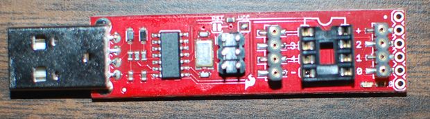
Solder the 2x3 pin male header into the empty 2x3 space on the Tiny AVR Programmer. The pins point up on the same side as the socket.
If you look closely at the first photo you will notice a small vertical line just to the left of the top left pin. This is the pin number one marker on the Tiny AVR Programmer.
On the board Pin number one is closest to the power supply.
Connect the ICSP cable like in the second photo.
Follow this link for instructions on how to add the Attiny84/85 definitions to the Arduino IDE: https://learn.sparkfun.com/tutorials/tiny-avr-pro...
Step 6: Pinouts and Testing

This is the pinout diagram for the Attiny84. If you are using the Arduino IDE use the numbers in brown.
To test your board hook up an LED with a resistor in series to each digital pin 0 - 10. Do not put an LED on physical pin four, that is reset.
Copy/Paste the following code into the Arduino IDE and upload it to your board:
int ledPins[] = {0,1,2,3,4,5,6,7,8,9,10}; <br>
/*****************************************************************
 * setup()
 *****************************************************************/
void setup()
{
  for(int i = 0; i < 11; i++)
  {
    pinMode(ledPins[i],OUTPUT);
  }
}


/*************************************************************
 * loop()
 *************************************************************/
void loop()
{
  for(int i = 0;i<11;i++)
  {
     digitalWrite(ledPins[i], HIGH);
     delay(250);
     digitalWrite(ledPins[i], LOW);
  }
}
Run it and the LEDs should blink on in sequence.
Attachments


Participated in the
Explore Science Contest


